[0006]The present invention has been made with the foregoing situation taken into consideration. An object of the present invention is to provide a vehicle differential device which is capable of efficiently taking lubricant oil in a transmission case into a differential case, particularly to rotation sliding portions between pinions (differential gears) and a pinion shaft (differential gear support portion), using a simple structure.
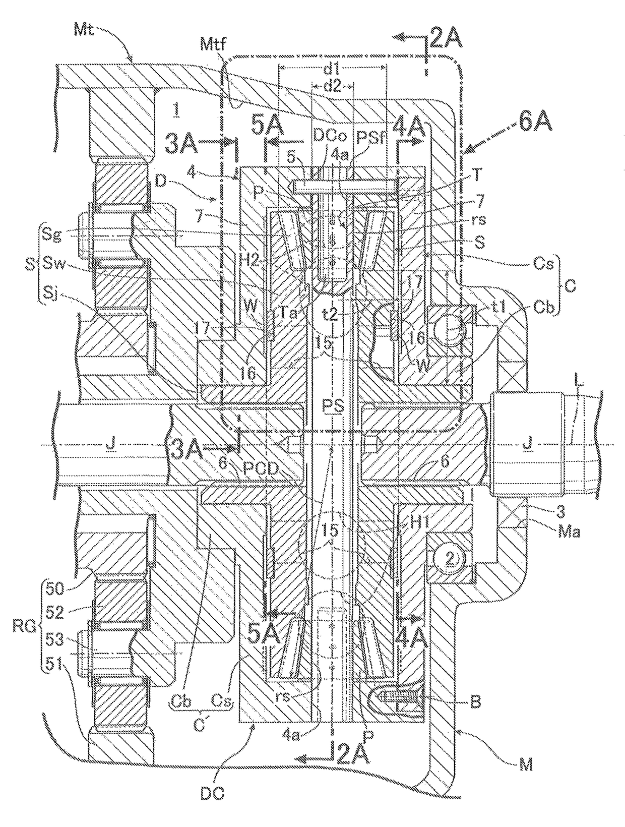
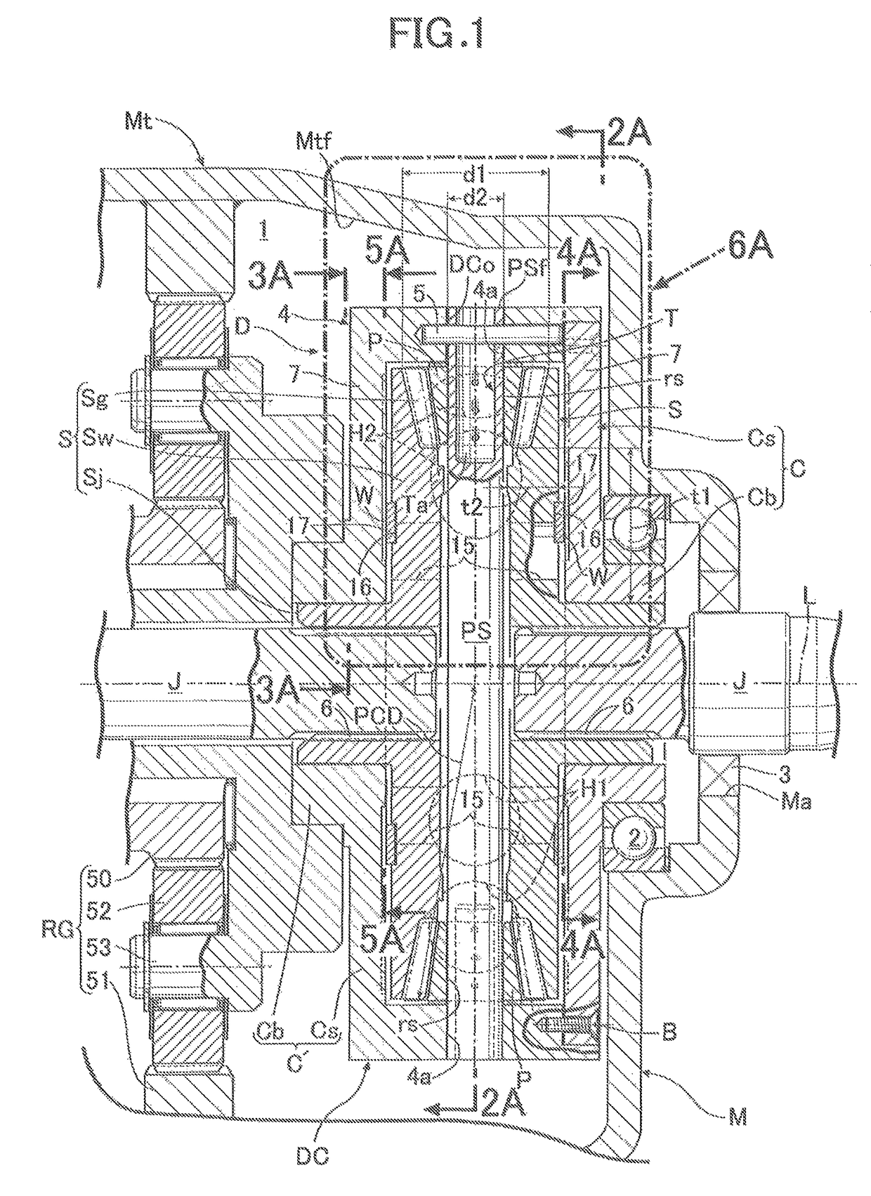
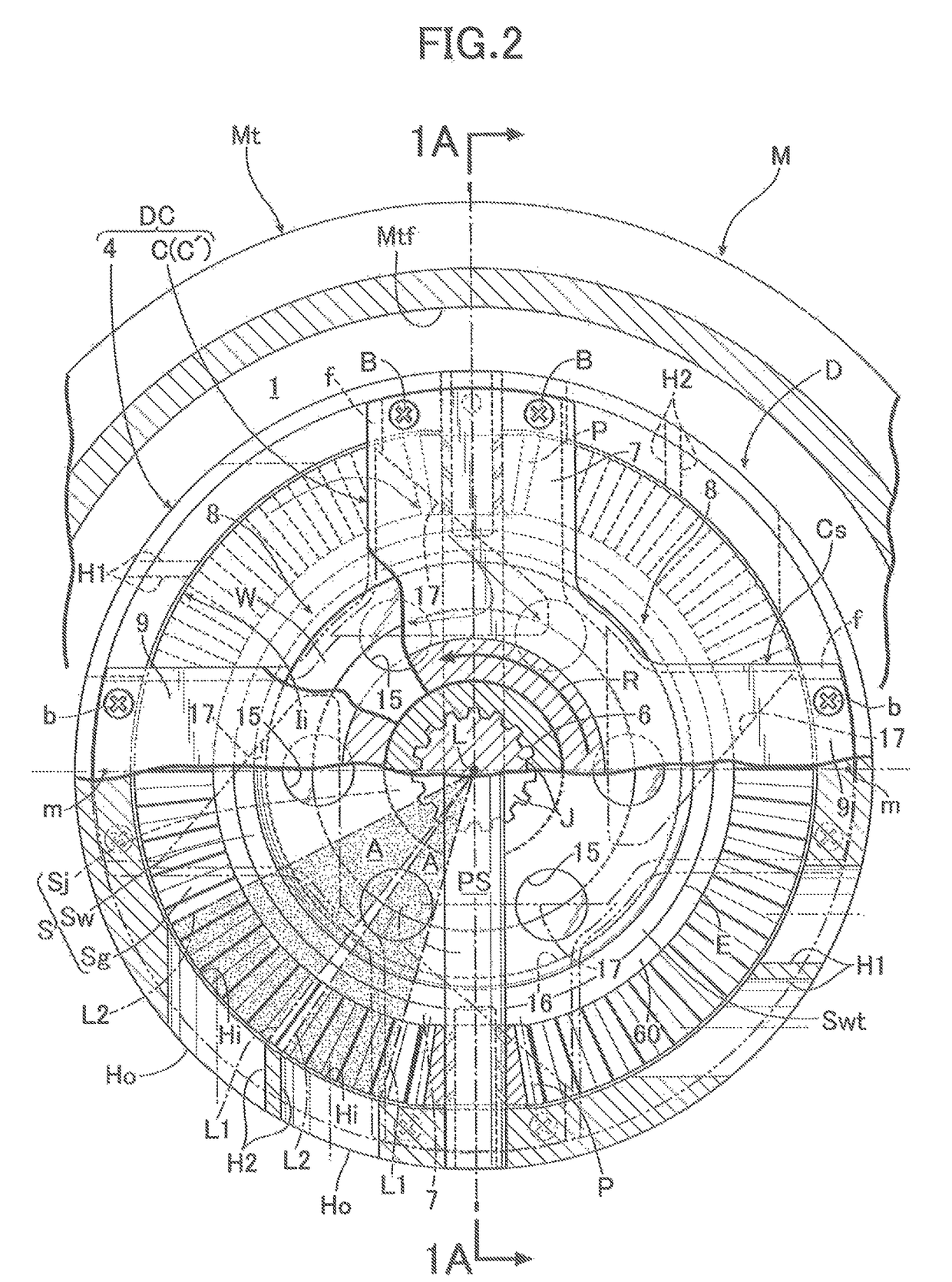
[0008]According to the first characteristic, the plurality of oil intake holes capable of taking the lubricant oil in the transmission case into the differential case are arranged in the outer peripheral wall of the differential case so as to be offset toward the pinions from the intermediate point between the two pinions positioned adjacent in the peripheral direction of the differential case; the oil intake holes are formed such that as seen in the projection plane orthogonal to the rotation axis of the differential case, the axes of the oil intake holes extending from the inner opening ends to the outer opening ends of the oil intake holes are inclined forward in the rotational direction of the differential case in forward traveling of the vehicle; and as seen in the projection plane, the pinions are placed outside the areas interposed between the first imaginary lines and the second imaginary lines, the first imaginary lines joining the rotation axis of the differential case and the one ends in the peripheral direction of the inner opening ends of the oil intake holes, the second imaginary lines joining the rotation axis of the differential case and the other ends in the peripheral direction of the inner opening ends of the oil intake holes. Thus, the lubricant oil in the transmission case can be efficiently taken into the differential case via the plurality of oil intake holes. Furthermore, among the plurality of oil intake holes, particularly the oil intake holes which are arranged in front of the pinions in the rotational direction and offset from the intermediate points toward the pinions are capable of efficiently supplying the lubricant oil which is taken into the differential case, to the meshing portions of the pinions and the side gears near the oil intake holes. Meanwhile, the other oil intake holes which are arranged in the back of the pinions in the rotational direction and offset from the intermediate points toward the pinions are capable of supplying the lubricant oil, which is taken into the differential case, to an outer peripheral portion of the pinion shaft near a rotation center of the differential case without the pinions hindering the supply of the lubricant oil (that is, without the pinions working as obstacles which block lubricant oil passages). The supplied lubricant oil flows, due to centrifugal force, along the outer peripheral surface of the pinion shaft toward the outer ends of the pinion shaft, that is, toward rotation sliding portions between the pinions and the pinion shaft. Thereby, the lubricant oil can be efficiently supplied also to the rotation sliding portions. As a result of these, the lubricant oil in the transmission case is efficiently supplied to not only the meshing portions of the pinions which are in mesh with the side gears, but also the rotation sliding portions between the pinions and the pinion shaft. Thereby, an overall lubricating effect can be enhanced.
[0010]According to the second characteristic, the side gears include: the shaft portions connected respectively to the pair of output shafts; the gear portions separating outward from the shaft portions in the radial direction; and the intermediate wall portions each having a plate shape and extending outward from the inner end portions of the shaft portions in the radial direction. Thus, a diameter of each side gear relative to a diameter of each pinion can be made as large as possible, so that the number of teeth of the side gear can be set sufficiently larger than the number of teeth of the pinion. This makes it possible to reduce load burden on the pinion shaft, and thus to decrease the diameter of the pinion shaft. This can accordingly contribute to a reduction in width of the differential case in the axial direction of the output shafts. Furthermore, even if as seen in the projection plane, the oil intake holes are located at the positions offset toward the pinions, the pinions are located outside the areas, that is, the diameter of each pinion is made sufficiently smaller than the diameter of each side gear. Thereby, although as described above, the oil intake holes are arranged to be offset toward the pinions (that is, closer to the pinions) in the peripheral direction of the differential case, the pinions can be arranged outside the areas corresponding to the inner opening ends of the oil intake holes without difficulties. This makes it possible to secure a sufficient effect of lubricating the rotation sliding portions between the pinions and the pinion shaft.
[0014]According to the third characteristic, the lubricant oil in the transmission case can be efficiently taken into the differential case via the plurality of oil intake holes. Furthermore, among the plurality of oil intake holes, particularly the oil intake holes which are arranged in front of the differential gears in the rotational direction of the differential case in forward traveling of the vehicle and are offset from the intermediate points toward the differential gears are capable of efficiently supplying the lubricant oil which is taken into the differential case, to the meshing portions of the differential gears and the output gears near the oil intake holes. Meanwhile, the other oil intake holes which are arranged in the back of the differential gears in the rotational direction and are offset from the intermediate points toward the differential gears are capable of supplying the lubricant oil which is taken into the differential case, to a portion of the differential gear support portion near the rotation center of the differential case without the differential gears hindering the supply of the lubricant oil (that is, without the differential gears working as obstacles which block lubricant oil passages). The supplied lubricant oil flows, due to centrifugal force, along the differential gear support portion toward the outer ends of the differential gear support portion, that is, toward rotation sliding portions between the differential gears and the differential gear support portion. Thereby, the lubricant oil can be efficiently supplied also to the rotation sliding portions. As these results, the lubricant oil in the transmission case is efficiently supplied to not only the meshing portions of the differential gears which are in mesh with the output gears, but also the rotation sliding portions between the differential gears and the differential gear support portion. Thereby, an overall lubricating effect can be enhanced. Moreover, according to the third characteristic, the differential device as a whole can be sufficiently reduced in width in the axial direction of the output shafts while securing the strength (for example, the static torsion load strength) and the maximum amount of torque transmission at approximately the same levels as the conventional differential device. Accordingly, the differential device can be easily incorporated in a transmission system, which is under many layout restrictions around the differential device, with great freedom and no specific difficulties, and is therefore advantageous in reducing the size of the transmission system.
[0017]According to the fourth and fifth characteristics, the differential device can be more sufficiently reduced in width in the axial direction of the output shafts while securing the strength (for example, the static torsion load strength) and the maximum amount of torque transmission at approximately the same levels as the conventional differential device.
[0019]According to the sixth characteristic, the cross sections of the oil intake holes orthogonal to the axes of the oil intake holes are each formed in a circular shape, that is, the cross sections are each formed in a shape which makes it easy to machine the oil intake holes. Thus, even when, for example, forging is employed to form the differential case whereby it is difficult to form the oil intake holes simultaneously, the oil intake holes can be easily machined after forming the differential case. This can contribute to a reduction in manufacturing costs.

