
Method for realizing internal walls of catalytic reactors

a technology of catalytic reactors and internal walls, which is applied in the direction of bulk chemical production, chemical/physical/physico-chemical processes, chemical apparatus and processes, etc., can solve the problems of high cost of manufacturing and assembly on-site, and high cost of internal wall parts, so as to reduce labor costs, reduce the number of parts required, and simplify the effect of internal wall construction

Active Publication Date: 2018-12-18
CASALE SA
View PDF7 Cites 0 Cited by
  • Summary
  • Abstract
  • Description
  • Claims
  • Application Information

AI Technical Summary

Benefits of technology

[0023]A major advantage of the invention, consequently, is that the single panels may have dimensions greater than the manhole available, since they can be bended for introduction owing to their flexibility. For example, the panels may be rolled up using suitable tools known per se (for example strapping tools as commonly used for industrial packing), until they can enter the available manhole. Furthermore, the panels may be rolled up and fastened, reducing their overall volume and the delivery costs, this being an important advantage in particular for revamping operations.
[0024]Owing to their elastic deformability (made possible by their small thickness), the panels follow the curvature of the cartridge wall. Moreover, since they do not carry out the load-bearing function, the joints between the panels may also be executed in a simple and cheap manner. Fixing together of the panels may be performed for example using bolts or known mechanical securing means. Removable connections may be provided between the panels, with the advantage of simplifying inspection, repair or replacement operations.
[0025]Another advantage of the elasticity of the panels consists in their capacity to compensate for expansion differences. Therefore the constructional design of the internal wall according to the invention easily withstands the thermal stress.
[0026]The reduced thickness also allows performing drilling and slotting operations necessary for the gas flow, by means of punching. It is known that punching is the most cost-effective perforation process, but can only be used when the size of the holes is approximately equal to (or greater than) the thickness of the metal sheet. On the other hand, containment of the catalyst requires fairly small holes and, therefore, punching generally cannot be performed in the prior art, where the collector has relatively thick walls and the minimum size of the holes which can be formed by punching would be too large. Thanks to the invention the collector has a small thickness and may be perforated by punching, resulting in significant savings.
[0027]In a preferred embodiment, the panels have a surface area comprising crests or ribs which are directed parallel to the axis of the reactor and which define lines of bearing contact against the load-bearing wall of the catalyst cartridge. For example, the panels may be made using corrugated metal sheet, and more preferably using so-called fretted metal sheet. By applying the invention to the construction of the outer collector, the crests act as spacers between the outer collector and the load-bearing wall of the cartridge, and thus define an interspace (annular cavity) for the gas flow between said two parts.
[0028]The fretted, or ribbed, metal sheet is particularly advantageous owing to the fact that the distance between collector and wall, i.e. the cross-section of the interspace, may be determined freely by the depth of the ribs, and is substantially independent from the distance between adjacent ribs (pitch). In other words, when changing the depth of the ribs, the pitch of the ribs may be determined independently of the gas flow cross-section between collector and cartridge. This feature is advantageous if compared to the use of a corrugated metal sheet, where the size of the gas through-flow interspace depends substantially on the wavelength of the corrugated metal sheet.

Problems solved by technology

The realization of these walls inside a vessel poses a number of technological challenges, in particular for the partially open reactors, which are the majority.
The partially open design is preferred because large-diameter flanges are costly and are a potential cause of leakage; however, the access inside the reactor is obviously conditioned by the relatively small diameter of the manhole.
This technique has the drawback of a high cost during both manufacture and assembly on-site.
The high costs arise from the number of parts required to form the internal wall and in particular the time required to perform long welds inside the vessel.
In the case of revamping of an existing apparatus, the need to reduce the assembly time assumes even greater importance since the time taken for revamping corresponds to loss of production due to plant shutdown, resulting in significant costs.
The construction of an internal wall may be further complicated by a manhole located in a poorly accessible position.
For example a manhole situated in a lateral or inclined position with respect to the axis of the apparatus (which is generally vertical) makes the introduction of the sections more difficult, thus resulting in the need to manufacture them with a smaller size, and increases the aforementioned costs.
The construction of the outer collector of radial flow reactors is particularly complicated because of both the large dimensions of the collector, which has a diameter similar to the diameter of the reactor itself, and the fact that, in many cases, said outer collector has a load-bearing function.
This constructional design has a number of recognized advantages from a functional point of view; however, for the reasons explained above, it may have high costs.
This design, however, poses a number of problems: the scallops do not surround the entire catalyst mass (but are immersed inside it) and the presence of the aforementioned play results in the catalyst coming into contact with the internal wall of the cartridge.
This results in the formation of catalyst zones which are not cooled, with the possible formation of hot spots and generation of by-products, and local heating of the cartridge.
Moreover, the scallops design results in high costs due to the large number of parts required to form the outer collector and due to the double-wall configuration.
For these reasons, the solution of the scallops design is not entirely satisfactory.

Method used


Image

  • Method for realizing internal walls of catalytic reactors
  • Method for realizing internal walls of catalytic reactors
  • Method for realizing internal walls of catalytic reactors

Examples


Embodiment Construction

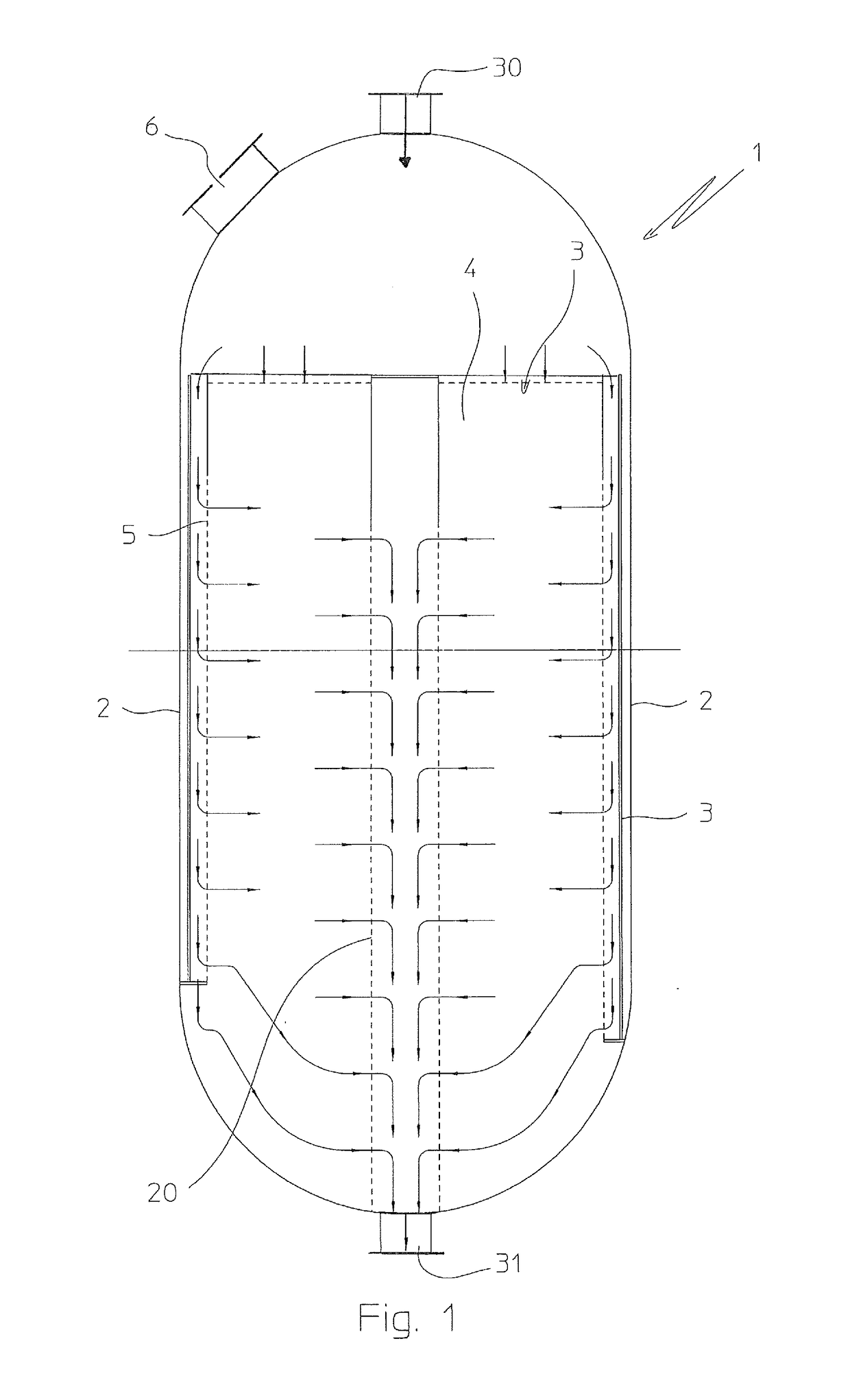
[0050]FIG. 1 shows a schematic illustration of a chemical reactor 1 with radial or axial-radial flow and centripetal (inward) flow, which essentially comprises: a partially open vessel 2, a catalyst cartridge 3 containing a catalyst bed 4 with the radial or axial-radial through-flow; an outer collector 5 arranged around the catalyst bed 4.

[0051]The partially open vessel 2 comprises a manhole 6 with a diameter smaller than the diameter of the vessel 2, a top inlet opening 30 and a bottom outlet opening 31 with a diameter smaller than the manhole 6.

[0052]The axial-radial through-flow of the bed 4 is achieved by means of the outer collector 5 and an inner collector 20.

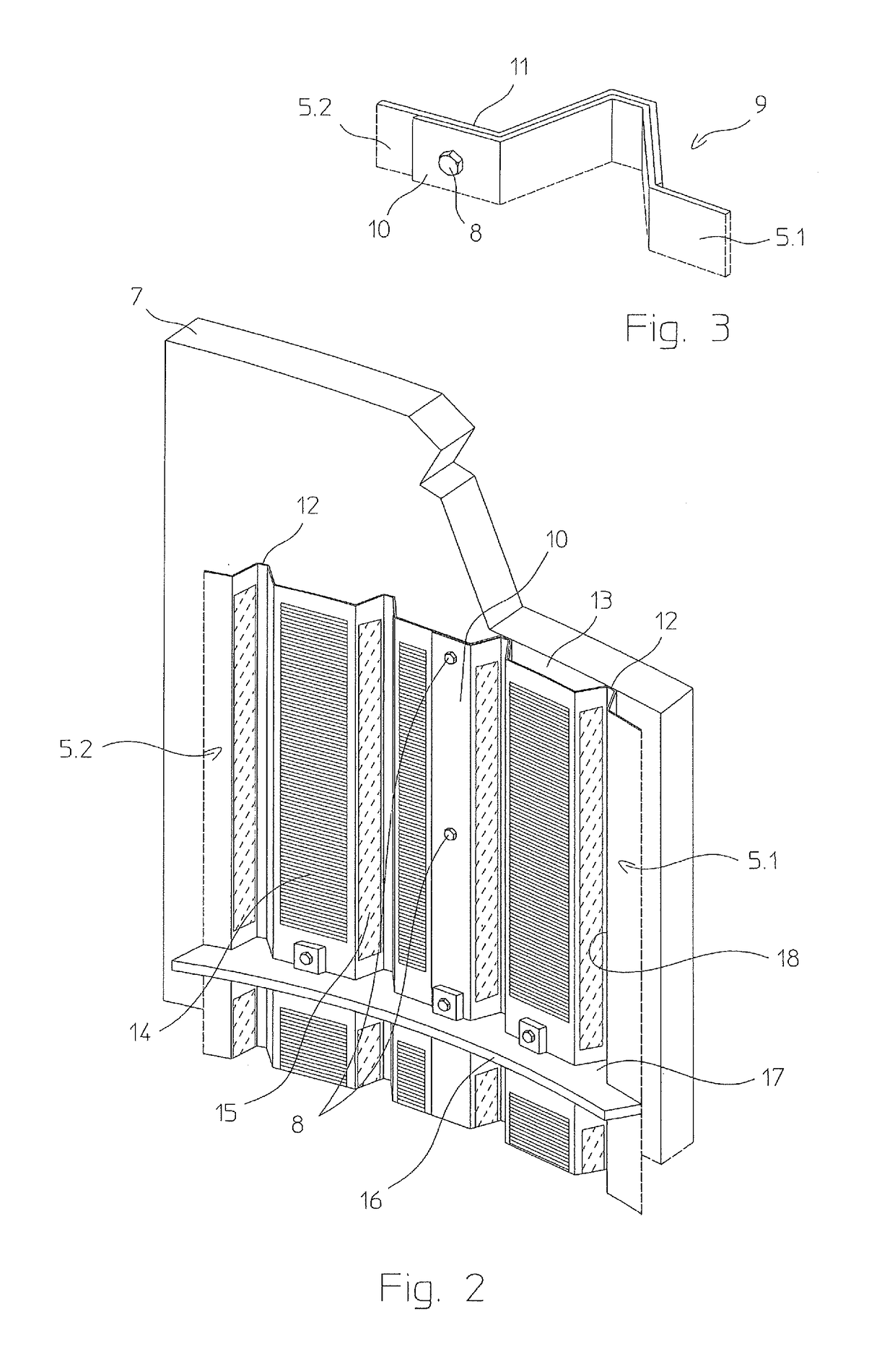
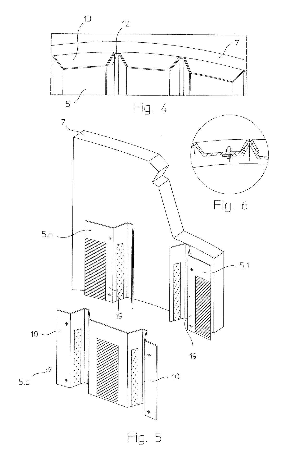
[0053]The outer collector 5 rests against the cartridge 3 and has a modular design, being formed substantially by a plurality of panels which can be inserted through the manhole 6 and / or through the top opening 30.

[0054]It should be noted that the collector 5 is flexible along its transverse extension, but is rigid longit...


PUM


Abstract

Reactor (1) for catalytic chemical reactions, comprising: a partially open outer vessel (2) comprising a manhole (6) for accessing to the interior, and at least one internal wall (5) comprising a plurality of panels (5.1, 5.2, . . . 5.n) assembled inside the vessel (2) so as to form said wall (5); the panels are flexible and deformable so that they may be inserted through said manhole (6), and the resulting wall (5) is not self-supporting and rests against a load-bearing wall (7) of the reactor.

Description

[0001]This application is a national phase of PCT / EP2015 / 077599, filed Nov. 25, 2015, and claims priority to EP 14199991.2, filed Dec. 23, 2014, the entire contents of both of which are hereby incorporated by reference.FIELD OF APPLICATION[0002]The invention relates to a method for realizing internal walls of catalytic reactors, in particular for realizing the outer collector of radial or axial-radial flow catalytic reactors.PRIOR ART[0003]In the field of catalytic chemical reactors there is the need to prepare walls inside the reactor vessel. Typically, these walls have the function of retaining the catalyst and conveying the flow of reagent gases. Among others, catalytic shift reactors, reactors for the synthesis of methanol and reactors for the ammonia synthesis are provided with internal walls called collectors.[0004]Radial or axial-radial flow catalytic reactors, for example, comprise a catalyst bed delimited by an internal wall (inner collector) and by an external wall (outer ...

Claims


Application Information

Patent Timeline
Patent Type & Authority Patents(United States)
IPC IPC(8): B01J8/02B01J8/00B01J19/02
CPCB01J8/0214B01J8/008B01J19/02B01J2219/0277B01J2208/027B01J2219/0002B01J8/0278B01J2208/00884B01J2208/0092B01J2219/00024Y02P20/52B01J8/00B01J8/02
Inventor RIZZI, ENRICO
Owner CASALE SA
Learn More