Air conditioner

a technology for air conditioners and fans, applied in lighting and heating apparatus, ventilation systems, heating types, etc., can solve the problems of generating wind noise (nz noise) and temporally spreading wind noise, and achieve the effects of suppressing wind noise, reducing wind noise, and reducing wind nois

Active Publication Date: 2018-12-18
DAIKIN IND LTD
View PDF50 Cites 1 Cited by
  • Summary
  • Abstract
  • Description
  • Claims
  • Application Information

AI Technical Summary

Benefits of technology

[0028]As described above, the following effects are obtained by the present invention.
[0029]According to the first aspect of the invention, the twisted portion provided in a region including the leading end side of at least one of the rear guider and the stabilizer is deviated from the axial direction gradually in the circumferential direction. On this account, wind noise (NZ noise) is not generated at once when one vane passes the twisted portion, with the result that the wind noise is continuously generated (i.e., in a spread manner). On this account, the wind noise is suppressed.
[0030]In addition to the above, the twisted portions occupy a certain length from the leading end of the stabilizer or the rear guider. Because this twisted portion is deviated from the axial direction gradually in the circumferential direction, the shape of the twisted portion is substantially uniform across any cross section orthogonal to the axial direction. On this account, a generated airflow is substantially on the same level as an airflow generated in case where the rear guider and the stabilizer linearly extend in parallel to the axial direction, and hence the deterioration of the air-blowing performance does not occur.
[0031]According to the third aspect of the invention, because the twisted portions are lined up in the axial direction, the degree of twist is high as compared to a case where a single twisted portion, the length of which in the axial direction is identical with the total length in the axial direction of the twisted portions, is provided. Furthermore, the twisted portion is provided in a range which is long in the axial direction. In addition to the above, when two neighboring twisted portions are deviated in different directions along the circumferential direction, wind noise may be large at the border of these two twisted portions on account of interference. In this regard, the twisted portions are deviated in the same direction along the circumferential direction, and hence the wind noise does not become large.
[0032]According to the fourth aspect of the invention, because the twisted portions are provided to oppose the respective vane wheels, wind noise is continuously generated by each of the vane wheels.
[0033]According to the fifth aspect of the invention, the direction of deviation in the circumferential direction between the end portions of two neighboring twisted portions which end portions oppose each other in the axial direction is identical with the direction of deviation in the circumferential direction between the vanes of two neighboring vane wheels. On this account, at the border between neighboring vane wheels, two or more vanes do not simultaneously pass a vortex airflow generated between the rear guider or the stabilizer and the fan, with the result that the wind noise is suppressed. When the deviation angles in the circumferential direction of these two are identical, wind noise is continuously generated from one end to the other end in the axial of the fan. This further suppresses the wind noise.

Problems solved by technology

When a vane of the fan passes this vortex airflow, wind noise (NZ noise) is generated on account of the interference between the vortex airflow and the vane.
With this arrangement, the edge of one vane does not simultaneously passes the apexes of the rib, and hence the generation of wind noise is temporally spread.

Method used


Image

  • Air conditioner
  • Air conditioner
  • Air conditioner

Examples


Embodiment Construction

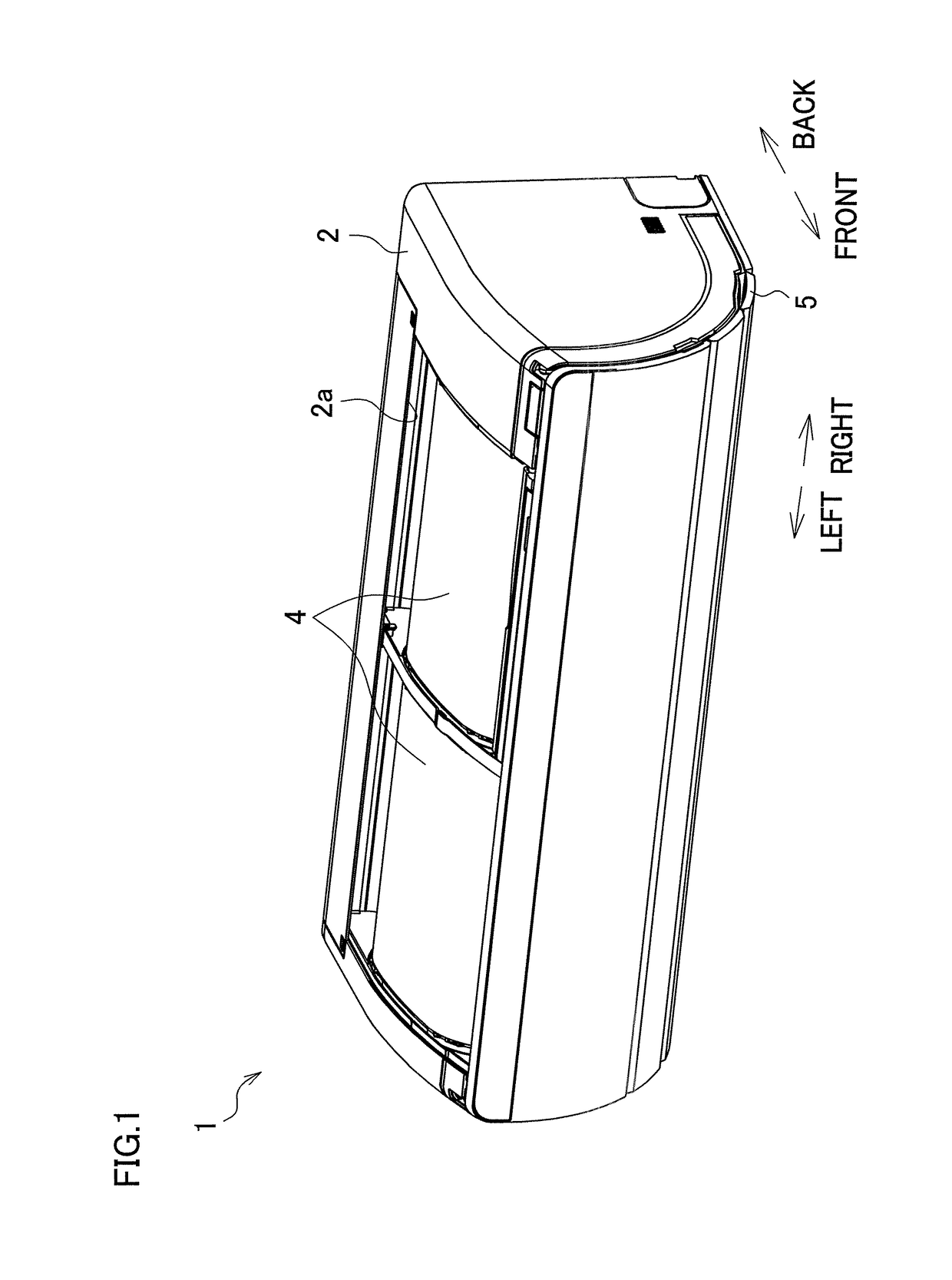
[0051]The following will describe an embodiment of the present invention. As shown in FIG. 1, an indoor unit 1 of an air conditioner of the present embodiment is as a whole narrow and long in one direction in shape, and is attached to a wall of a room so that the length of the air conditioner is horizontal. The indoor unit 1 and an unillustrated outdoor unit constitute the air conditioner which cools or warms the room. Hereinafter, a direction of protrusion from the wall to which the indoor unit 1 is attached will be referred to as “frontward”, whereas the direction opposite to the frontward will be referred to as “backward”. Furthermore, the left-right direction in FIG. 1 will be simply referred to as “left-right direction”.

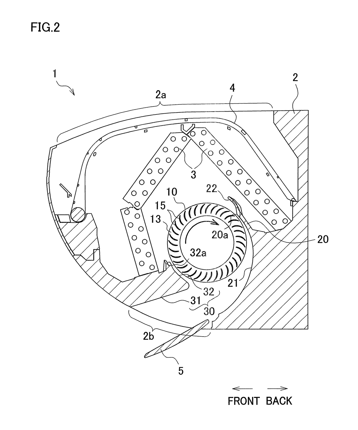
[0052]As shown in FIG. 2, the indoor unit 1 includes a casing 2 and internal devices stored in the casing 2 such as a heat exchanger 3, a cross flow fan 10, a filter 4, and an electronic component box (not illustrated). Through the upper surface of the casing 2 ...


PUM


Abstract

Wind noise is suppressed while an air-blowing performance is maintained.An indoor unit 1 of an air conditioner includes a cross flow fan 10 and a rear guider 20 and a stabilizer 32 which are provided on the respective sides of the outer periphery of the cross flow fan 10 to form an air passage. Each of the rear guider 20 and the stabilizer 32 has, at least at a part in the axial direction which part is on the leading end side, twisted portions 23, 37. In the circumferential direction of the cross flow fan 10, each twisted portion 23, 37 is deviated from the axial direction of the cross flow fan 10 gradually from one end to the other end.

Description

TECHNICAL FIELD[0001]The present invention relates to an air conditioner including a cross flow fan.BACKGROUND[0002]A cross flow fan is a blower which extends in the axial direction and includes a plurality of vanes lined up in the rotational direction. In an air conditioner including this cross flow fan, a stabilizer and a rear guider are provided to oppose the outer periphery of the fan, respectively. The stabilizer is termed a front tongue portion, whereas a part of the rear guider which part extends from the leading end portion to the portion closest to the fan is termed a rear tongue portion. These tongue portions form an air passage on the blow-out side of the fan. Between each tongue portion and the fan, a vortex airflow is generated. When a vane of the fan passes this vortex airflow, wind noise (NZ noise) is generated on account of the interference between the vortex airflow and the vane.[0003]To suppress this wind noise, for example, Patent Document 1 teaches that a rib pro...

Claims


Application Information

Patent Timeline
Patent Type & Authority Patents(United States)
IPC IPC(8): F04D17/04F24F1/00F24F7/08F04D29/28F04D29/42F04D29/66F04D29/44
CPCF24F7/08F04D17/04F04D29/283F04D29/422F04D29/665F04D29/666F24F1/0025F04D29/441F24F2001/0048F24F1/0003F24F13/24F24F2013/247F24F1/0057
Inventor NAKAI, SATOSHIUDA, MASAFUMI
Owner DAIKIN IND LTD
Why Eureka
Try Eureka