Image processing apparatus and image processing method

a technology of image processing and image, applied in the direction of instruments, static indicating devices, etc., can solve the problems of image quality degradation, image cannot be applied to a self-luminous display, image wholly becomes dark, etc., to reduce power consumption of display units, reduce luminance, and reduce image luminance

Active Publication Date: 2018-12-25
SONY CORP
View PDF17 Cites 1 Cited by
  • Summary
  • Abstract
  • Description
  • Claims
  • Application Information

AI Technical Summary

Benefits of technology

[0014]According to one aspect of the present disclosure, it is possible to reduce luminance. Further, according to one aspect of the present disclosure, when power consumption of a display unit is reduced by reducing luminance of an image, it is possible to suppress degradation of image quality.

Problems solved by technology

However, this technology cannot be applied to a self-luminous display such as an organic light-emitting diode (OLED) display.
However, with the technology of reducing luminance by uniformly multiplying luminance of an image by a gain less than 1, an image wholly becomes dark.
Further, with the technology of reducing luminance of a region having predetermined characteristics, because a reduction amount of luminance cannot be finely controlled, image quality degrades.
Further, although there is a technology of controlling a tone curve as a technology for reducing power consumption of a self-luminous display, contrast of the whole screen becomes too high.

Method used


Image

  • Image processing apparatus and image processing method
  • Image processing apparatus and image processing method
  • Image processing apparatus and image processing method

Examples


second embodiment

(Configuration Example of Second Embodiment of Image Processing Apparatus)

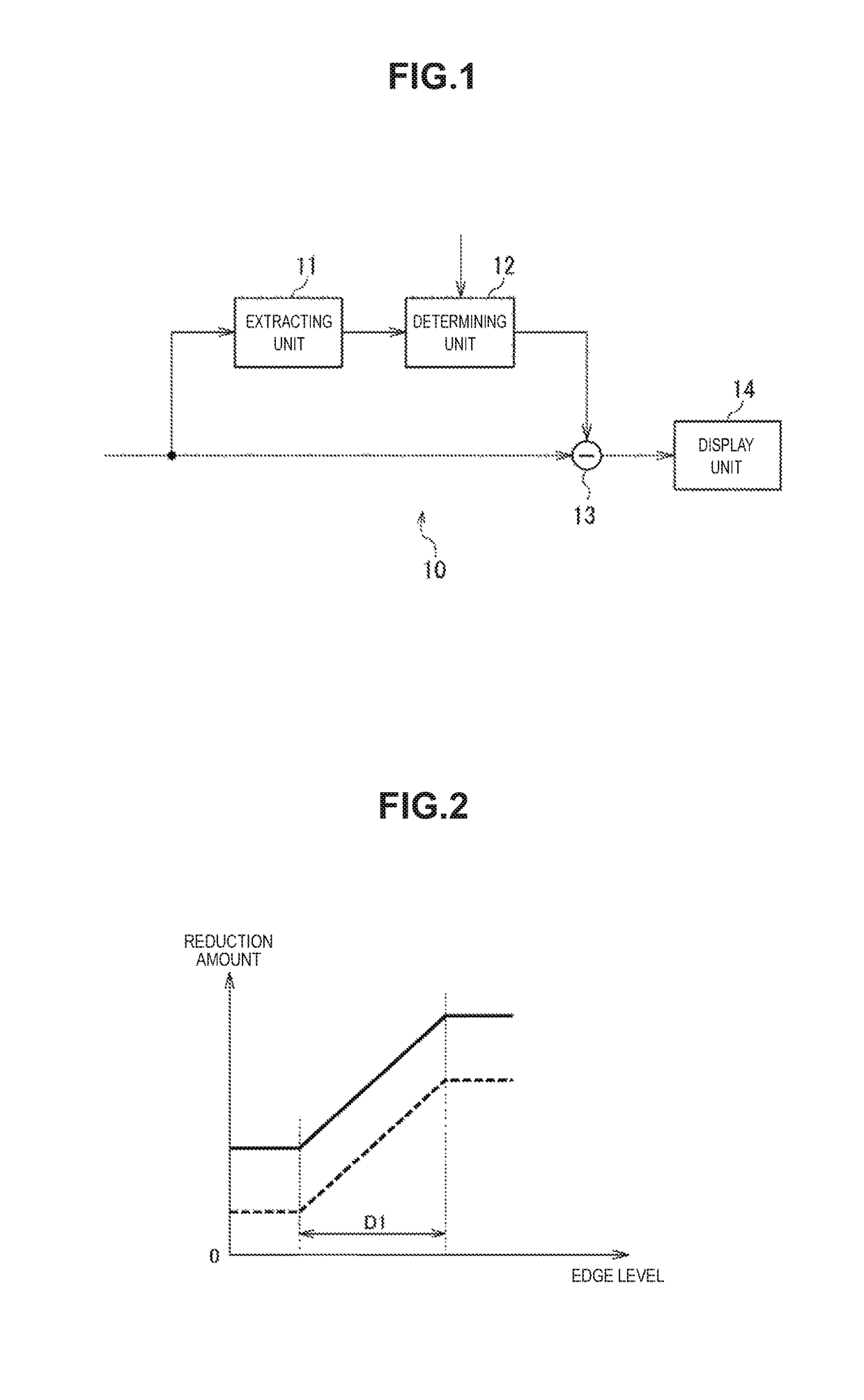
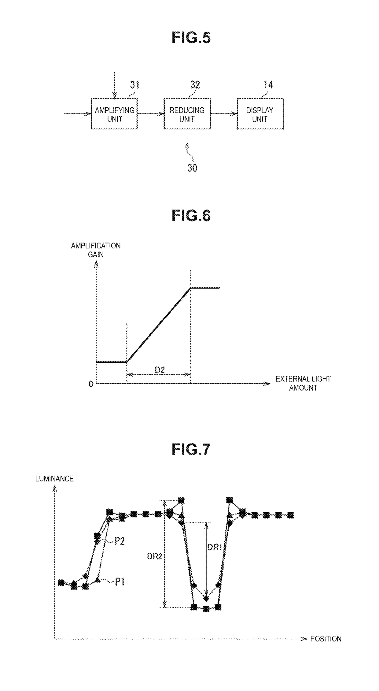
[0068]FIG. 5 is a block diagram illustrating a configuration example of a second embodiment of the image processing apparatus to which the present disclosure is applied.

[0069]Among components illustrated in FIG. 5, the same reference numerals are assigned to the components which are the same as the components in FIG. 1. Overlapped explanation will be omitted as appropriate.

[0070]The image processing apparatus 30 in FIG. 5 is configured with an amplifying unit 31, a reducing unit 32 and a display unit 14. The image processing apparatus 30 reduces power consumption of the display unit 14 by reducing the luminance of the input image after amplifying alternating current (AC) components of the luminance of the input image.

[0071]Specifically, the amplifying unit 31 of the image processing apparatus 30 compensates for the AC components by amplifying the AC components of the luminance of the input image with an amplif...

third embodiment

(Configuration Example of Third Embodiment of Image Processing Apparatus)

[0099]FIG. 12 is a block diagram illustrating a configuration example of a third embodiment of the image processing apparatus to which the present disclosure is applied.

[0100]Among the components illustrated in FIG. 12, the same reference numerals are assigned to the components which are the same as the components in FIG. 1 or FIG. 5. Overlapped explanation will be omitted as appropriate.

[0101]The configuration of the image processing apparatus 50 in FIG. 12 is different from the configuration in FIG. 1 in that an amplifying unit 31 and a reducing unit 51 are provided in place of the reducing unit 13. The image processing apparatus 50 is a combination of the image processing apparatus 10 and the image processing apparatus 30, and reduces the luminance of the input image in which the AC components of the luminance are amplified by a reduction amount for each pixel of the input image.

[0102]Specifically, the reduc...


PUM


Abstract

The present disclosure relates to an image processing apparatus, an image processing method, and a program which can suppress degradation of image quality when power consumption of a display unit is reduced by reducing luminance of an image. A determining unit determines a reduction amount of luminance of a pixel based on characteristics of each pixel of an input image. A reducing unit reduces the luminance of the pixel of the input image by the reduction amount determined by the determining unit. The present disclosure can be applied to, for example, an image processing apparatus, or the like, which reduces luminance of a pixel based on characteristics of each pixel of an input image and displays the input image whose luminance is reduced.

Description

CROSS REFERENCE TO RELATED APPLICATIONS[0001]This application is a U.S. National Phase of International Patent Application No. PCT / JP2015 / 057838 filed on Mar. 17, 2015, which claims priority benefit of Japanese Patent Application No. 2014-073505 filed in the Japan Patent Office on Mar. 31, 2014. Each of the above-referenced applications is hereby incorporated herein by reference in its entirety.TECHNICAL FIELD[0002]The present disclosure relates to an image processing apparatus, an image processing method, and a program, and, more particularly, to an image processing apparatus, an image processing method, and a program which can suppress degradation of image quality when power consumption of a display unit is reduced by reducing luminance of an image.BACKGROUND ART[0003]A technology for reducing power consumption of a display is an important technology in, particularly, a long period of use of battery-powered mobile equipment such as a smartphone and a tablet terminal. As a technolo...

Claims


Application Information

Patent Timeline
Patent Type & Authority Patents(United States)
IPC IPC(8): G09G3/34G09G3/36G09G3/30G09G3/20
CPCG09G3/3406G09G3/20G09G3/30G09G3/36G09G2320/0233G09G2360/16G09G2320/0295G09G2320/066G09G2320/0626G09G2330/021G09G2320/0271G09G2320/043
Inventor KAMIO, KAZUNORINAGANO, TAKAHIROZHU, YIWENICHIHASHI, HIDEYUKI
Owner SONY CORP
Why Eureka
Try Eureka