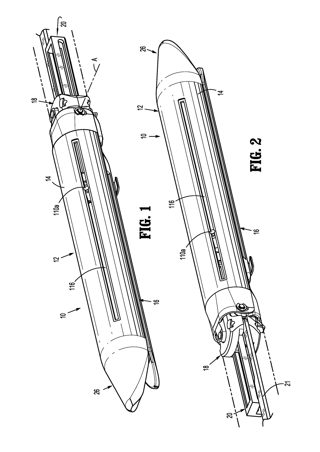
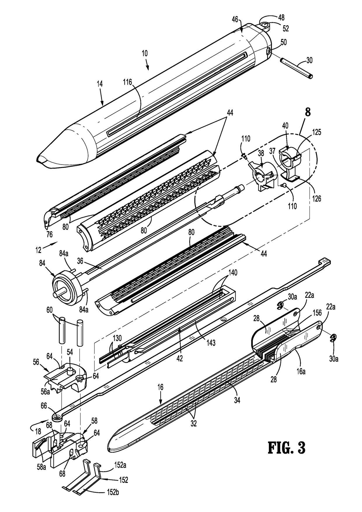
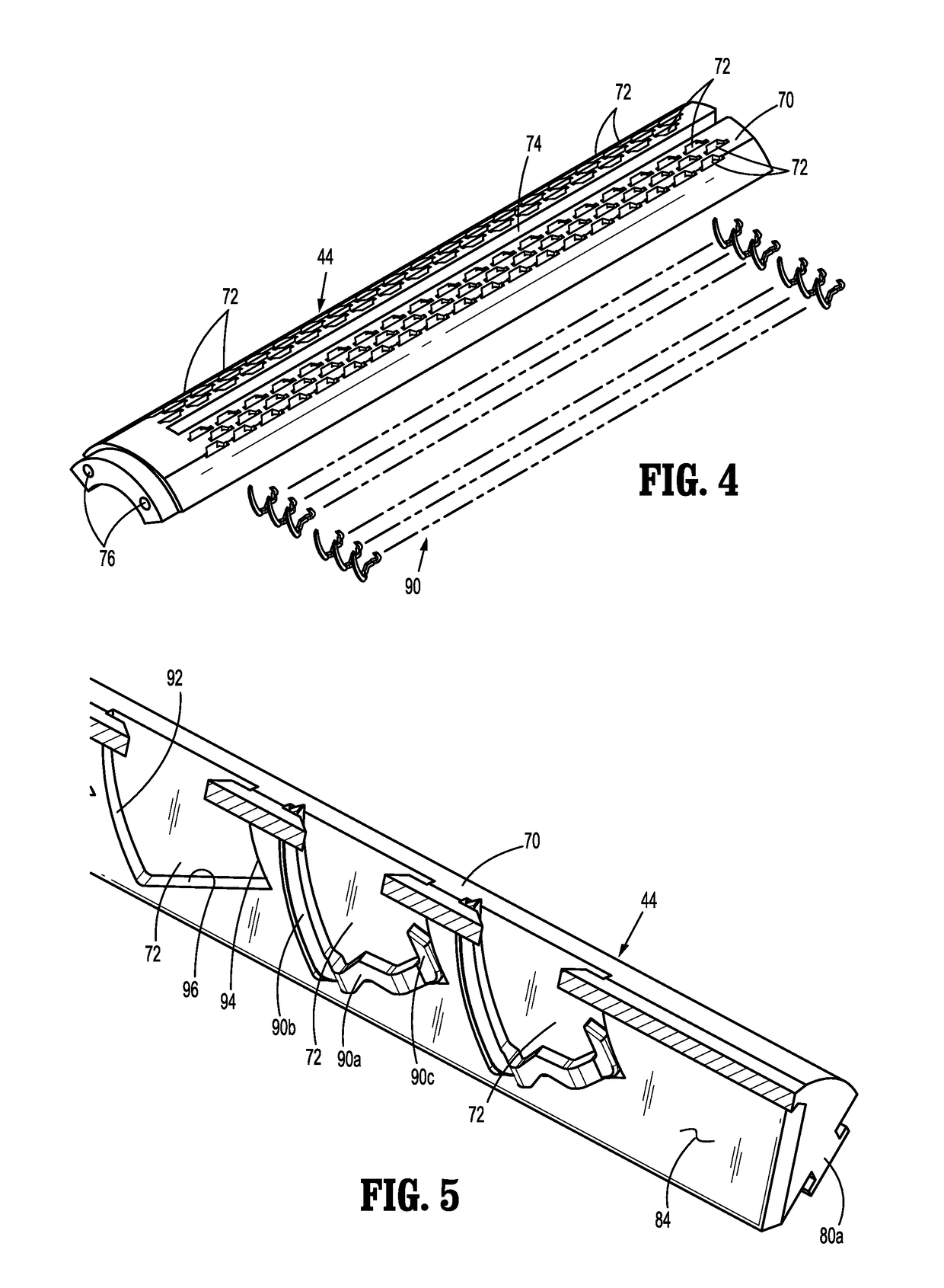
Multi-fire push rod stapling device

a push rod and multi-fire technology, applied in the field of surgical stapling devices, can solve the problems of increasing the time required for surgical procedures, increasing the likelihood of infection,

Active Publication Date: 2019-01-08
TYCO HEALTHCARE GRP LP +1
View PDF1430 Cites 635 Cited by
  • Summary
  • Abstract
  • Description
  • Claims
  • Application Information

AI Technical Summary

Benefits of technology

[0017]In embodiments, the clamping member includes a hub positioned about the guide shaft, a vertical strut extending radially outwardly of the hub and a beam supported on an end of the vertical strut and extending transversely of the vertical strut. Each of the cartridges of the plurality of cartridges and the anvil define a knife slot. The vertical strut is positioned to extend through the knife slots of the cartridge in the active position and of the anvil to position the beam in engagement with an outer surface of the anvil such that distal movement of the clamping member within the cartridge assembly causes the anvil to move from the open position to the clamped position.
[0021]In embodiments, the mounting member defines an elongated slot that receives the pivot pin and the cartridge housing defines an elongated through bore that receives the pivot pin. The pivot pin is movable within the elongated slot of the mounting member and the elongated through bore of the cartridge housing to facilitate movement of the pivot pin and the proximal end of the anvil in relation to the proximal end of the mounting member and the proximal end of the cartridge housing.

Problems solved by technology

This process increases the time required to perform the surgical procedure and increases the likelihood of infection.

Method used


Image

  • Multi-fire push rod stapling device
  • Multi-fire push rod stapling device
  • Multi-fire push rod stapling device

Examples


Embodiment Construction

[0062]Embodiments of the present disclosure are now described in detail with reference to the drawings in which like reference numerals designate identical or corresponding elements in each of the several views. As used herein, the term “clinician” refers to a doctor, a nurse, or any other care provider and may include support personnel. Throughout this description, the term “proximal” refers to the portion of the device or component thereof that is closest to the clinician and the term “distal” refers to the portion of the device or component thereof that is farthest from the clinician. In addition, the term “endoscopic procedures” as used herein refers to any procedure performed through a small incision in the skin or through one or more cannulas and encompasses laparoscopic procedures, arthroscopic procedures, etc.

[0063]As described in detail below, the presently disclosed surgical stapling device includes a barrel, formed by a plurality of cartridges connected to each other, tha...


PUM


Abstract

A surgical stapling device includes a housing and a plurality of cartridges that are coupled together to form a barrel that is rotatably supported within the housing. Each of the cartridges defines a plurality of staple pockets, each supporting a staple. An anvil is coupled to the housing and is movable in relation to the barrel between an open position and a clamped position. A guide shaft extends through the housing and through the barrel. The guide shaft supports a sled and a clamping member. The sled is configured to translate through the barrel to eject the staples from an active cartridge of the plurality of cartridges in response to actuation of a push rod. After firing staples from the active cartridge, the sled and the guide shaft are configured to index or rotate the barrel within the housing to move a second cartridge of the plurality of cartridges to the active position upon retraction and subsequent movement of the sled through a second firing stroke.

Description

CROSS-REFERENCE TO RELATED APPLICATIONS[0001]This application claims the benefit of and priority to U.S. Provisional Patent Application No. 62 / 166,969 filed May 27, 2015, the entire disclosure of which is incorporated by reference herein.BACKGROUND[0002]Technical Field[0003]The present disclosure relates generally to a surgical stapling device for applying surgical fasteners to body tissue. More particularly, the present disclosure relates to an endoscopic surgical stapling device having a plurality of staple cartridges that are sequentially moved into alignment with an anvil assembly to allow a clinician to fire the stapling device a plurality of times without removing the stapling device from the surgical site.[0004]Background of Related Art[0005]Surgical stapling devices for joining tissue sections are commonly used in surgical procedures. The use of surgical stapling devices as compared to traditional stitching techniques reduces the time required to join and / or cut tissue, thus...

Claims


Application Information

Patent Timeline
Patent Type & Authority Patents(United States)
IPC IPC(8): A61B17/04A61B17/10A61B17/072A61B17/00A61B90/00A61B17/29
CPCA61B17/07207A61B2017/0046A61B2017/00199A61B2017/00398A61B2090/035A61B2017/07285A61B2017/2927A61B2090/034A61B2017/07271A61B17/0644A61B2017/07278
Inventor MARCZYK, STANISLAWGROVER, SIMON R.WARD, ALISTAIRSTACEY, GARY
Owner TYCO HEALTHCARE GRP LP
Why Eureka
Try Eureka