
Device and method for 3D printing with long-fiber reinforcement

a technology of 3d printing and long fibers, applied in the direction of additive manufacturing processes, manufacturing tools, and applying layer means, etc., can solve the problems of requiring immense hand labor to fabricate, expensive and time-consuming process, and thermoset resins,

Active Publication Date: 2019-01-08
NORTHROP GRUMMAN SYST CORP
View PDF38 Cites 14 Cited by
  • Summary
  • Abstract
  • Description
  • Claims
  • Application Information

AI Technical Summary

Benefits of technology

The invention is a process and device for 3D printing parts using advanced composite materials reinforced with long-fiber reinforcements. The nozzle has a filament inlet for introducing polymer material, a filament passage where the polymer material is heated and a fiber inlet where a fiber is introduced. The fiber is encapsulated in the polymer material and severed at a work surface using a cutting device. The invention also includes a method for 3D printing a fiber-reinforced advanced composite part by introducing viscous thermosetting resin, reinforcing fibers, and depositing the advanced composite on a work surface. The invention allows for the creation of strong and lightweight parts using advanced composite materials.

Problems solved by technology

The design and manufacturing of advanced composites usually employ very complicated processes and machinery that involve saturating the fiber with the resin, then causing the resin to bind, typically in a mold apparatus.
For most manufacturing processes, thermoset resins, and increasingly thermoplastic resins, require immense hand labor to fabricate, multiple repetitive processes, and often autoclave (pressure vessel) curing.
This is an expensive and time consuming process, with little room for error.
Repeating this process several times eventually results in the buildup of enough thickness to contain the finished part.
This technique only allows for entire plies to be placed, and not individual fibers, and generates a large amount of waste material in the “cubing / de-cubing” process.
However, all of these 3D printed items lack one important attribute, the ability to be used as structural components with significant loads beyond simple low compressive loading.
But, these advanced composites typically come with a large price tag (due in part to increased material, design, and manufacturing costs) that is significantly beyond that of the metallic structures they replace.

Method used


Image

  • Device and method for 3D printing with long-fiber reinforcement
  • Device and method for 3D printing with long-fiber reinforcement
  • Device and method for 3D printing with long-fiber reinforcement

Examples


Embodiment Construction

[0036]If used and unless otherwise stated, the terms “upper,”“lower,”“front,”“back,”“over,”“under,” and similar such terms are not to be construed as limiting the invention to a particular orientation. Instead, these terms are used only on a relative basis.

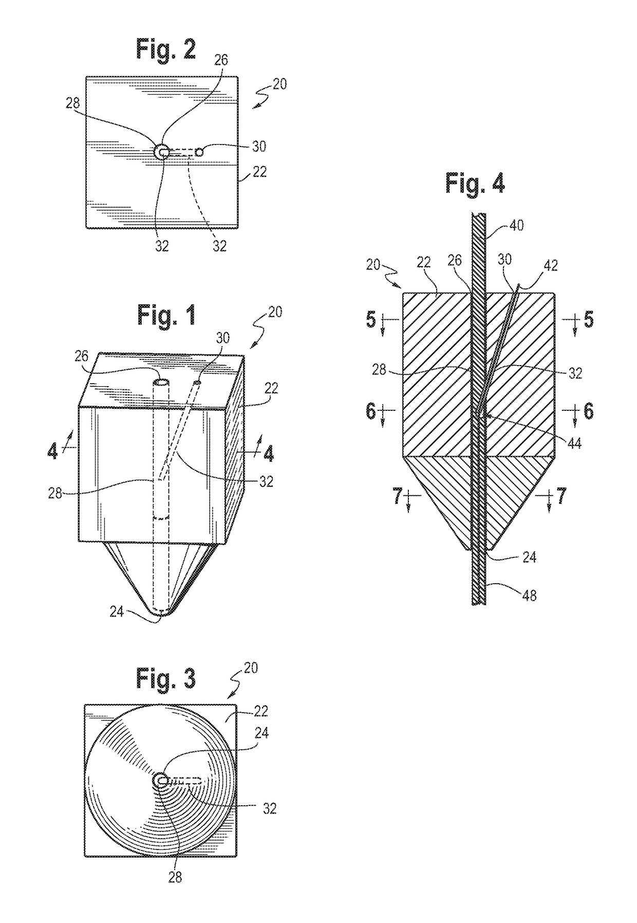
[0037]FIG. 1 depicts a nozzle 20 for use in a 3D printing apparatus. Nozzle 20 has a nozzle body 22. Although representative outer shapes for nozzle 20 and nozzle body 22 are shown, one of ordinary skill in the art would understand that a variety of shapes, for example, a cylinder, could be used.

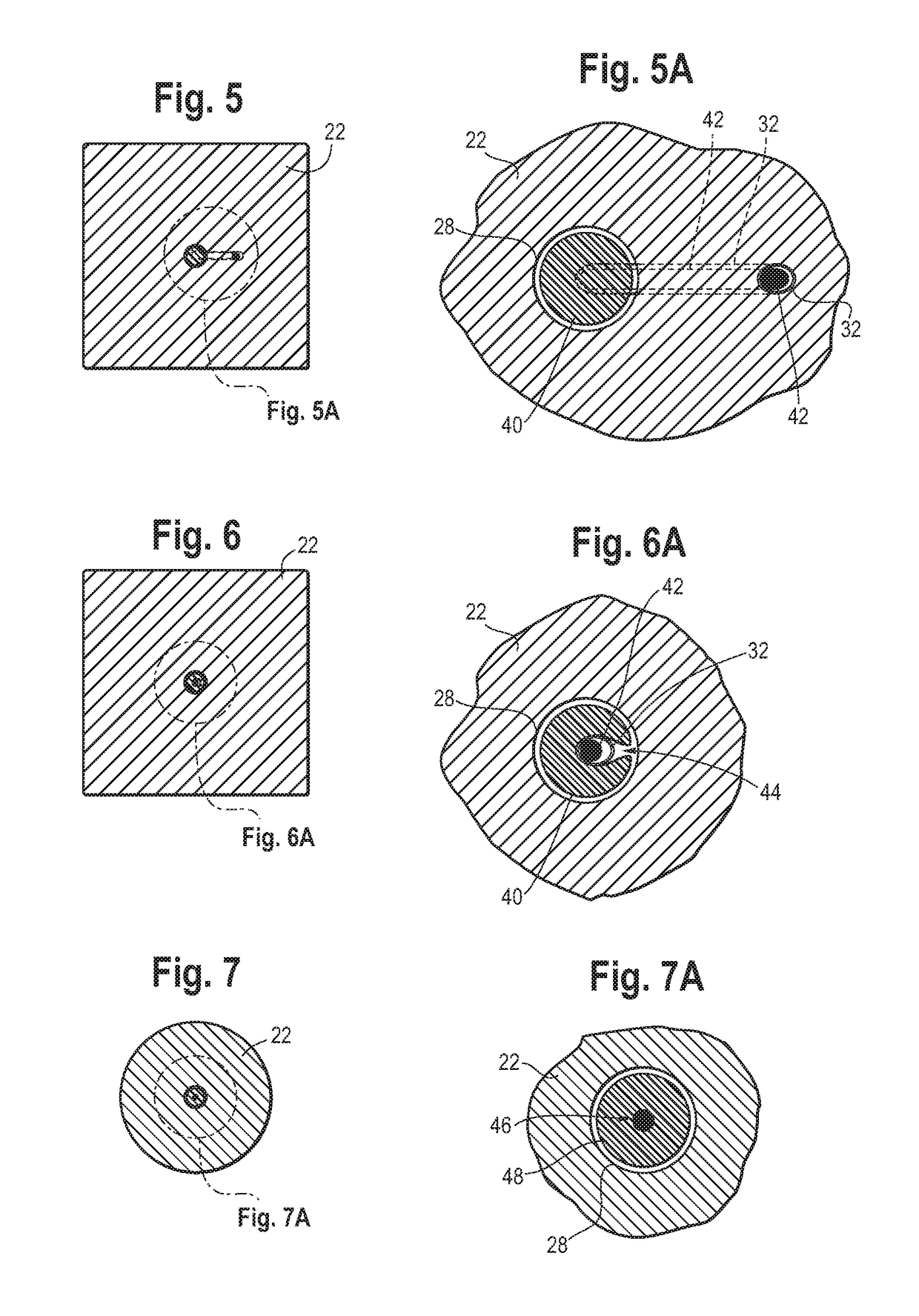
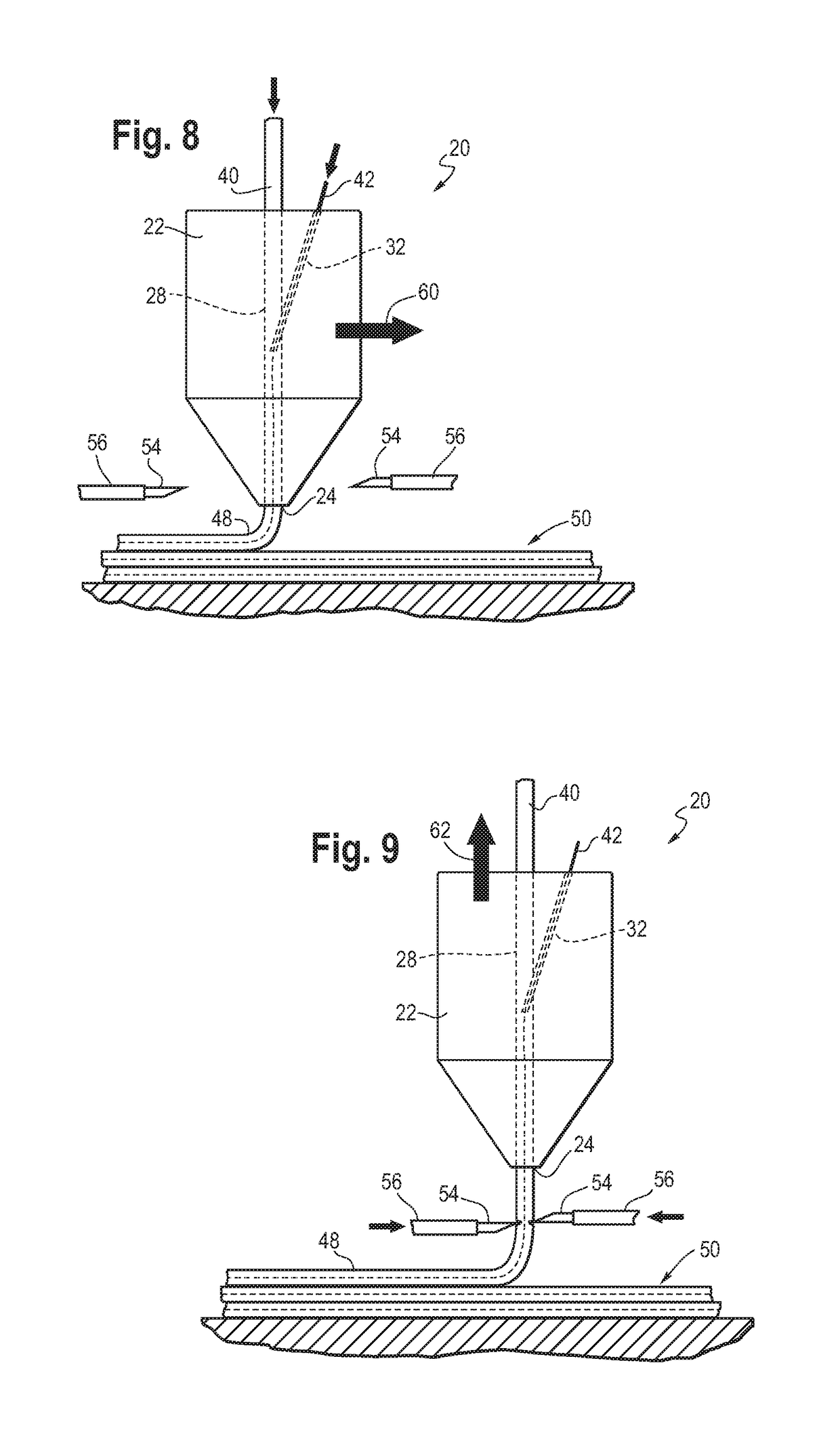
[0038]Nozzle body 22 includes an inlet 26 for receiving a filament to be used in 3D printing. In an embodiment, the filament is a thermoplastic filament, but as an alternative, a thermosetting resin or other similar polymer material could be used. The following discussion relates to the thermoplastic filament embodiment, modifications for using the invention with a thermosetting resin are discussed below. After entering filament inlet 26, ...


PUM

PropertyMeasurementUnit
melting pointaaaaaaaaaa
angleaaaaaaaaaa
thermoplasticaaaaaaaaaa

Abstract

A process and device for 3D printing parts incorporating long-fiber reinforcements in an advanced composite material is disclosed. A nozzle for a 3D printing device receives a polymer material and a reinforcing fiber through separate inlets. A passage from the reinforcing fiber inlet cleaves the passage containing the polymer material, creating an interstitial cavity into which the reinforcing fiber is introduced. The polymer material closes back on itself and encapsulates the reinforcing fiber, then drags the fiber along with the flow and exits nozzle to be deposited on a work surface or part being manufactured.

Description

FIELD OF THE INVENTION[0001]The invention relates generally to three-dimensional (3D) printers and more particularly to 3D printing with long-fiber reinforcement.BACKGROUND OF THE INVENTION[0002]A number of technologies are used to manufacture non-metallic structural components capable of sustaining significant loads. Typically these involve composite materials that combine a resin with some type of fiber reinforcement. Advanced composites have been developed that use expensive, high-performance resins and fiber reinforcement with properties of high strength and stiffness. The design and manufacturing of advanced composites usually employ very complicated processes and machinery that involve saturating the fiber with the resin, then causing the resin to bind, typically in a mold apparatus. For most manufacturing processes, thermoset resins, and increasingly thermoplastic resins, require immense hand labor to fabricate, multiple repetitive processes, and often autoclave (pressure ves...

Claims


Application Information

Patent Timeline
Patent Type & Authority Patents(United States)
IPC IPC(8): B29C67/00B33Y10/00B33Y30/00B29C64/165B29C64/20B29C64/40B29C48/05B29C48/30B29K101/10B29K105/08
CPCB33Y30/00B29C47/128B29C64/165B29C64/40B33Y10/00B29C64/20B29K2105/08B29K2101/10B29C48/0022B29C64/209B29C48/02B29C64/118B29K2101/12B29C48/34B29C48/2883B29C48/266B29C64/30B29C48/05B29C48/304B29C48/30
Inventor NARDIELLO, JERRELL A.CHRIST, ROBERT J.CRAWFORD, JOHN A.MADSEN, JOHN S.
Owner NORTHROP GRUMMAN SYST CORP
Learn More