Foldable display device and holding structure thereof

a display device and folding technology, applied in the direction of display/control unit casings, electrical apparatus casings/cabinets/drawers, identification means, etc., can solve problems such as damage to display panels, and achieve the effect of reducing the tensile stress on the flexible display panel and preventing damag

Active Publication Date: 2019-01-22
E INK HLDG INC
View PDF20 Cites 3 Cited by
  • Summary
  • Abstract
  • Description
  • Claims
  • Application Information

AI Technical Summary

Benefits of technology

[0022]In the aforementioned embodiments of the present invention, because the first supporting stage is located above the first inner housing, and the first supporting stage and the first inner housing are connected to the first spring element through the first hinge, a side of the first supporting stage may pivot on the first hinge, and another side of the first supporting stage may stretch or compress the first spring element. Similarly, a side of the second supporting stage may pivot on the second hinge, and another side of the second supporting stage may stretch or compress the second spring element. When the foldable display device is changed to a folded state from a spread state, although a tensile stress may be formed by the flexible display panel in a crosswise and outward direction due to bending, the first and second spring elements have elastic forces and the first and second supporting stages are movable. Therefore, the effect of the tensile stress upon the flexible display panel may be reduced due to the elastic forces of the first and second spring elements, such that the difference of combined stress among the flexible display panel, the first and second supporting stages is reduced. As a result, the flexible display panel is prevented from separating from the first and second supporting stages, and is prevented from being damaged by a stress concentration position of the tensile stress and an adhesive force.

Problems solved by technology

Alternatively, a stress concentration position of the tensile stress and the adhesive force may damage the display panel.

Method used


Image

  • Foldable display device and holding structure thereof
  • Foldable display device and holding structure thereof
  • Foldable display device and holding structure thereof

Examples


Embodiment Construction

[0030]Reference will now be made in detail to the present embodiments of the invention, examples of which are illustrated in the accompanying drawings. Wherever possible, the same reference numbers are used in the drawings and the description to refer to the same or like parts.

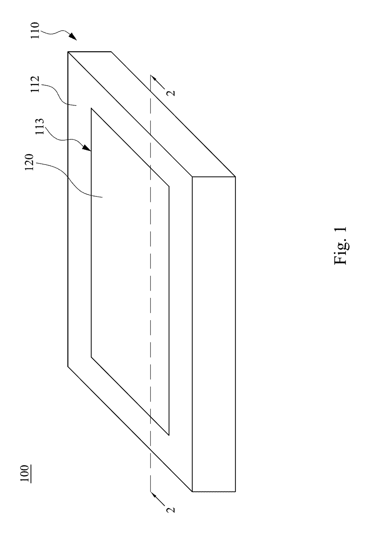
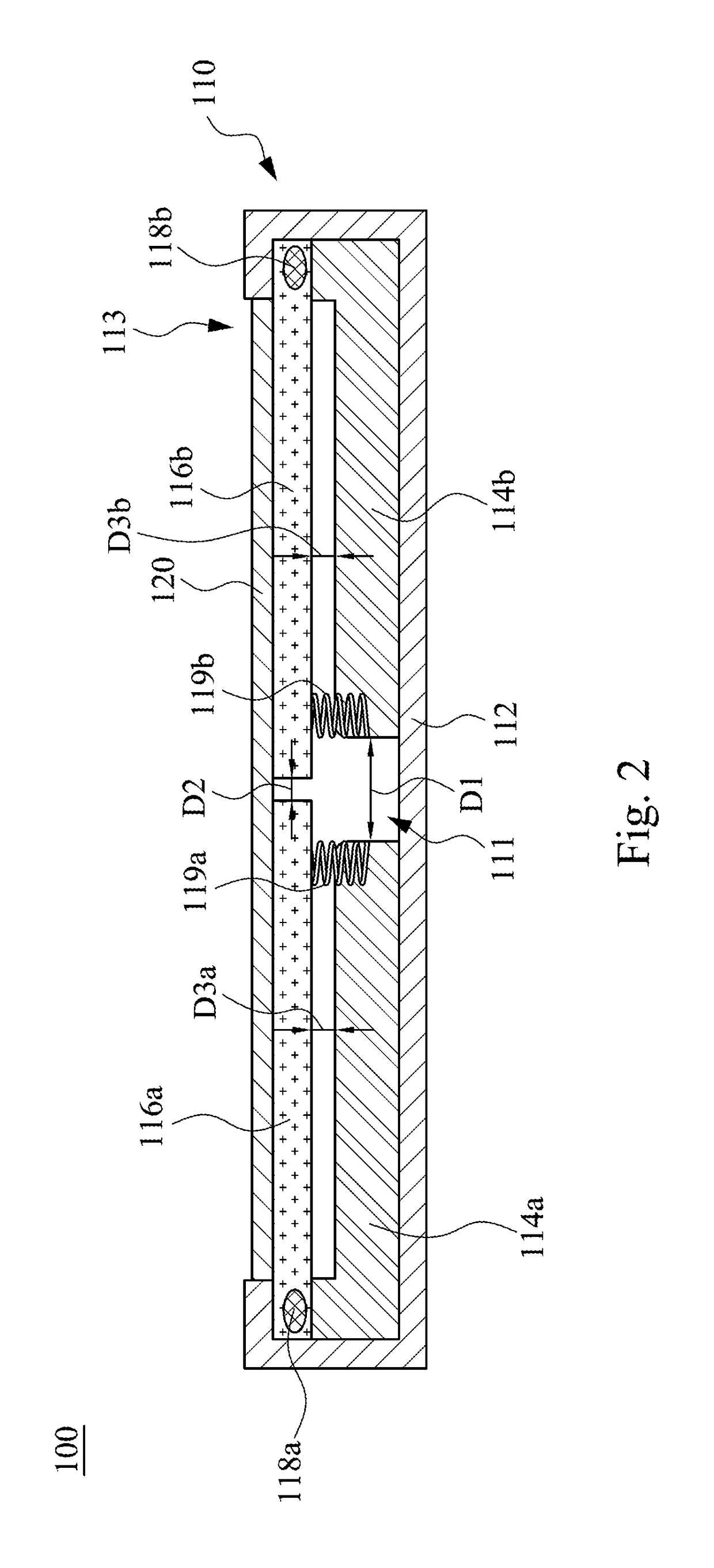
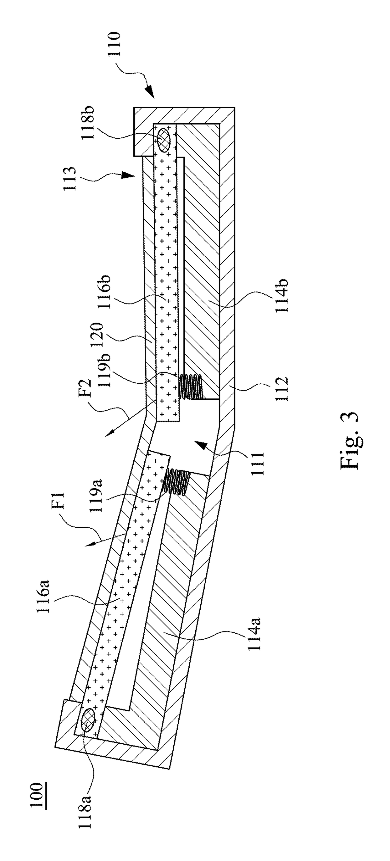
[0031]FIG. 1 is a perspective view of a foldable display device 100 according to one embodiment of the present invention, in which the foldable display device 100 is in a spread state. FIG. 2 is a cross-sectional view of the foldable display device 100 taken along line 2-2 shown in FIG. 1. As shown in FIG. 1 and FIG. 2, the foldable display device 100 includes a holding structure 110 and a flexible display panel 120. The holding structure 110 may be utilized to support the flexible display panel 120. The holding structure 110 includes a soft outer housing 112, a first inner housing 114a, a second inner housing 114b, a first supporting stage 116a, a second supporting stage 116b, a first hinge 118a, a first spri...


PUM


Abstract

A foldable display device includes a holding structure and a flexible display panel. The holding structure includes a soft outer housing, a first inner housing, a second inner housing, a first supporting stage, a second supporting stage, a first hinge, a first spring element, a second hinge, and a second spring element. The first hinge is connected to a same side of the first inner housing and the first supporting stage. The first spring element is connected to another same side of the first inner housing and the first supporting stage. The second hinge is connected to a same side of the second inner housing and the second supporting stage. The second spring element is connected to another same side of the second inner housing and the second supporting stage. The flexible display panel is located on the first and second supporting stages.

Description

RELATED APPLICATIONS[0001]This application claims priority to China Application Serial Number 201611087958.4, Dec. 1, 2016, which is herein incorporated by reference.BACKGROUND[0002]Field of Invention[0003]The present invention relates to a foldable display device and a holding structure of the foldable display device.[0004]Description of Related Art[0005]Since foldable display panels (such as electrophoretic display panels) have been presented to the public, foldable display devices have been available in the market of electronic products today. A foldable display device has a foldable housing, and a flexible display panel is disposed on the foldable housing. A user may spread or fold the display panel by unfolding or folding the housing. In general, the housing may have two portions that are connected by hinges, and the flexible display panel is disposed on two supporting stages that are respectively in the two portions of the housing, and the flexible display panel presents a spr...

Claims


Application Information

Patent Timeline
Patent Type & Authority Patents(United States)
IPC IPC(8): H05K5/00H05K5/02
CPCH05K5/0017H05K5/0226H05K5/0217H05K5/0004G09F9/301H04M1/0268G06F1/1616G06F1/1652G06F1/1681H04M1/0216
Inventor YEH, CHIA-CHUNCHENG, KUO-HSINGLIN, YI-SHENG
Owner E INK HLDG INC
Why Eureka
Try Eureka