
Support systems and methods for a transportation system

a transportation system and support system technology, applied in transportation and packaging, elevated railways, ways, etc., can solve the problems of increasing the overall cost of the transportation system, unsettling passengers, and discomfort of passengers aboard the vehicle, and achieve the effect of reducing deflection

Inactive Publication Date: 2019-01-29
THE BOEING CO
View PDF9 Cites 2 Cited by
  • Summary
  • Abstract
  • Description
  • Claims
  • Application Information

AI Technical Summary

Benefits of technology

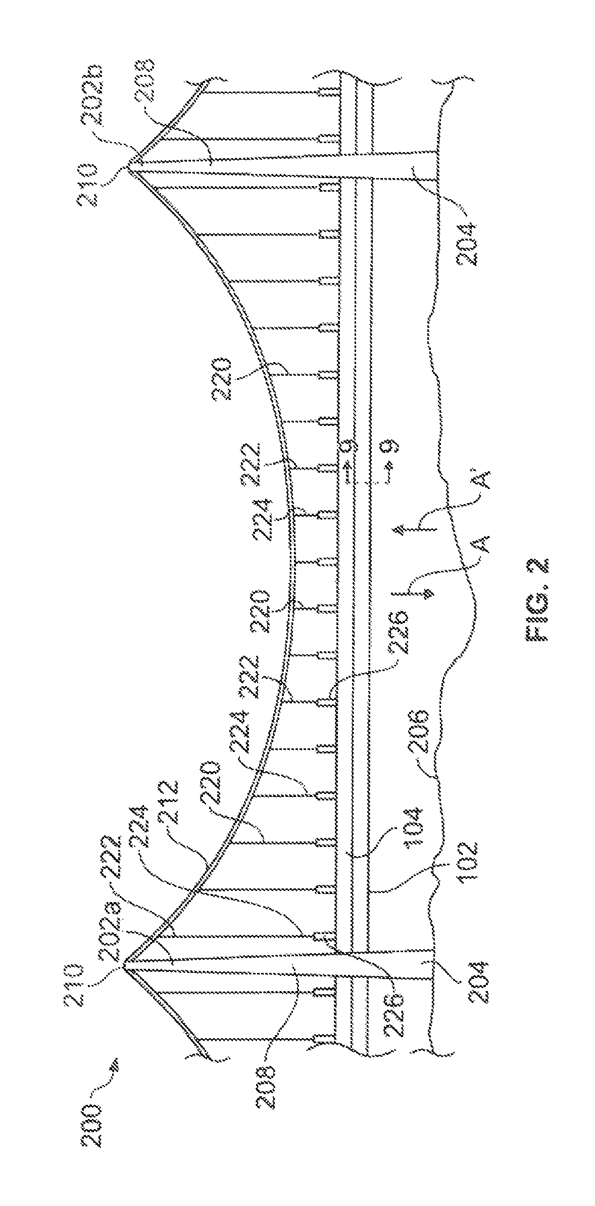
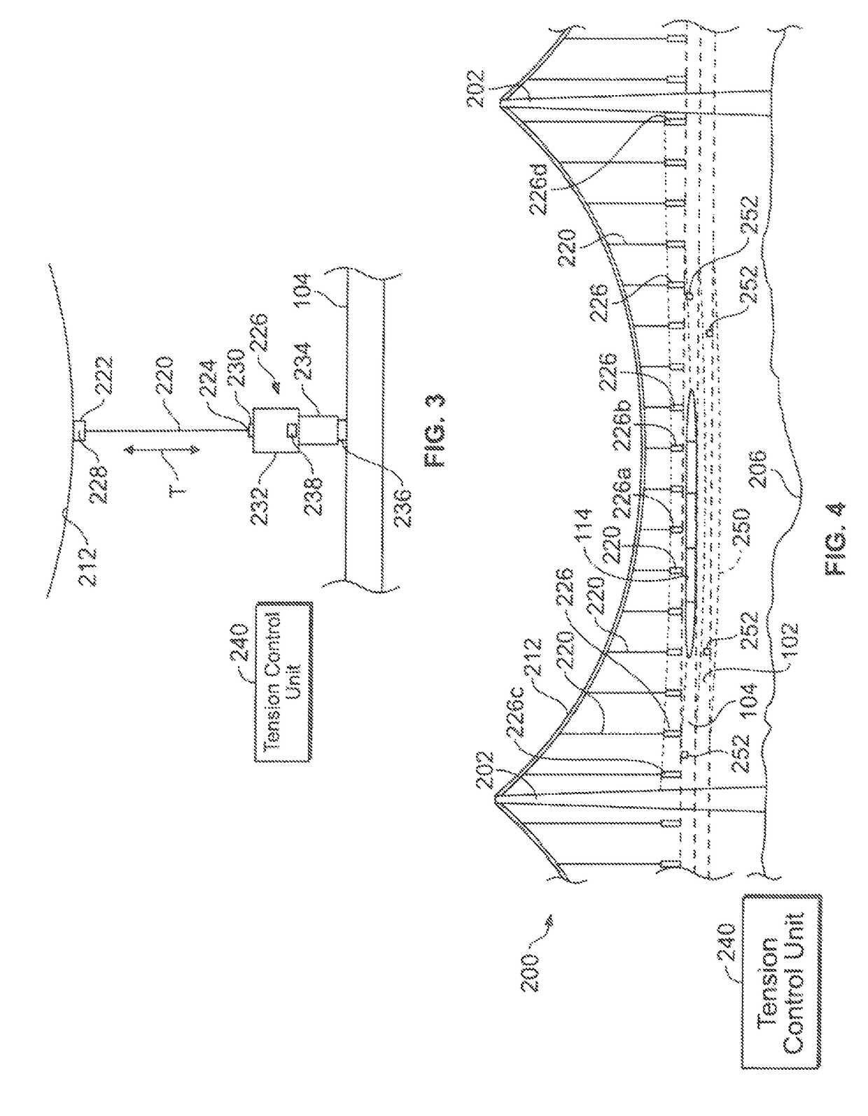
The patent text describes a system and method for supporting an above ground tube to reduce deflections when vehicles travel through the tube. The system uses a vacuum to create a vacuum inside the tube to minimize aerodynamic drag on the vehicle. The method also involves supporting a suspension cable between support towers, positioning the tube between the towers, and using a tension support member to pull the tube towards the suspension cable. The tension force is adjusted when the vehicle passes through the interior channel to reduce deflection of the tube. The technical effect of this patent is to provide a more stable, efficient, and cost-effective method for supporting an above ground tube transportation system.

Problems solved by technology

The deflections of the tube under vertical load applied by the vehicle traveling therein may be unsettling to passengers.
Such a magnitude of deflection may cause discomfort to passengers aboard the vehicle traveling through the tube.
As can be appreciated, tubes of increased size and weight increase the overall cost of the transportation system.
Again, however, reducing the spacing between support columns requires an increased number of support columns, which increases the overall cost of the transportation system.
However, the process of tunneling substantially increases the cost of the transportation system.
Overall, tunnels are more expensive than above ground systems.
As such, the increased pressure may require stronger (and expensive) tubes to be used.

Method used


Image

  • Support systems and methods for a transportation system
  • Support systems and methods for a transportation system
  • Support systems and methods for a transportation system

Examples


Embodiment Construction

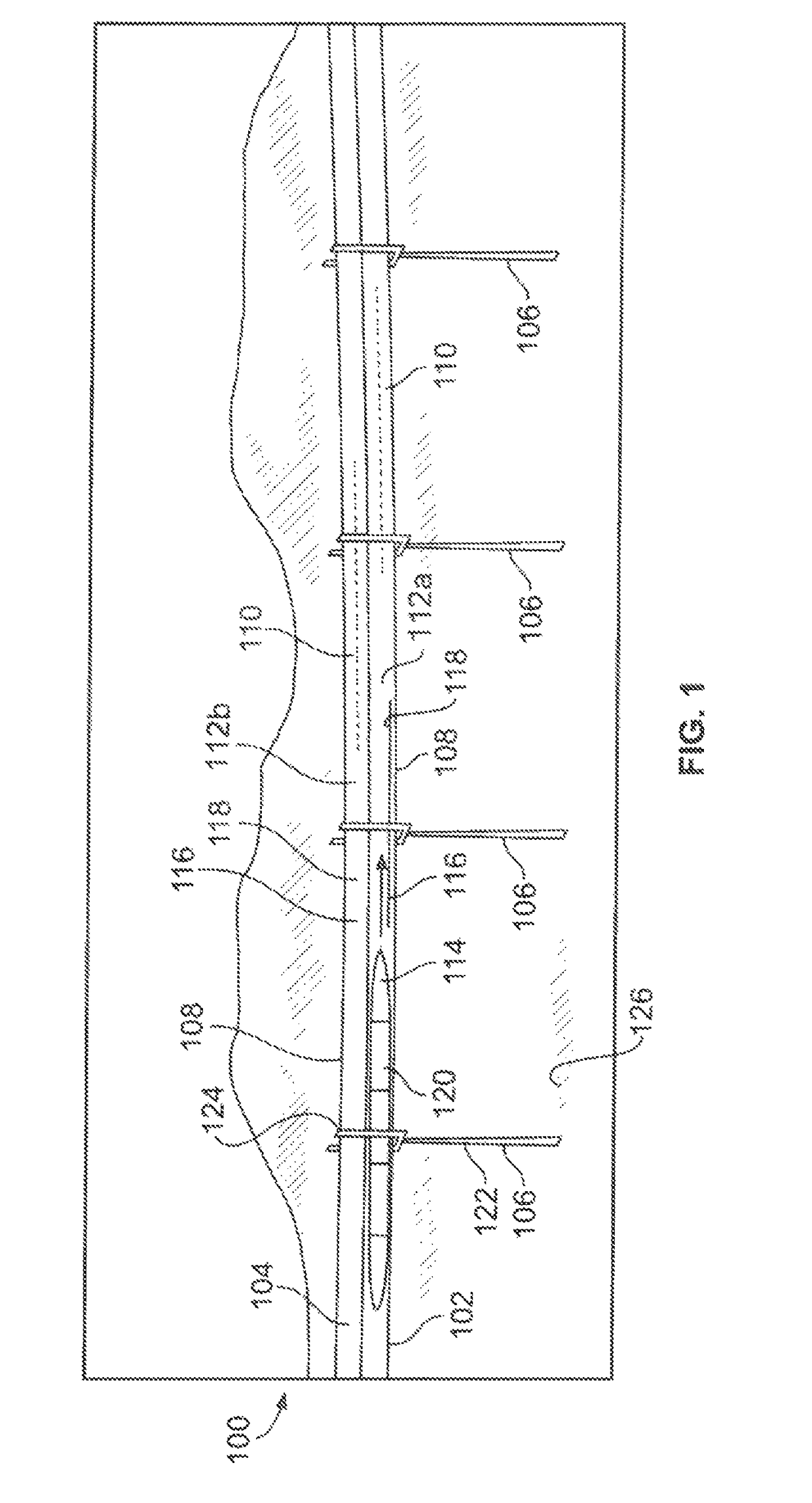
[0001]Embodiments of the present disclosure generally relate to transportation systems, and, more particularly, to systems and methods of supporting vehicles that travel through tubes supported above a surface of the ground.

BACKGROUND OF THE DISCLOSURE

[0002]Magnetic levitation is a form of transportation in which a vehicle is moved via magnetic levitation without contacting the ground. As such, the vehicle is able to move without experiencing rolling friction with the ground or support rails, for example. In general, the vehicle travels along a guideway via magnets that generate lift and propulsion, thereby reducing friction and allowing travel at high speeds.

[0003]Currently, magnetic levitation systems are being developed in which a vehicle travels through vacuum tubes, in order to reduce the effects of aerodynamic drag on the vehicle. As such, the speed and operational efficiency of the vehicle are increased through the elimination or reduction of air friction with respect to the ...


PUM


Abstract

A transportation system includes a first support tower, a second support tower, a suspension cable extending between the first and second support towers, and a tube defining an interior channel extending between the first and second support towers. A vehicle is configured to travel through the interior channel. A tension support member has a first end coupled to the suspension cable and a second end coupled to the first tube through an actuator. The tension support member exerts tension force to upwardly pull the first tube towards the suspension cable. The actuator adjusts the tension force when the vehicle travels through the interior channel under the tension support member to reduce deflection of the tube.

Description

FIELD OF EMBODIMENTS OF THE DISCLOSURE[0001]Embodiments of the present disclosure generally relate to transportation systems, and, more particularly, to systems and methods of supporting vehicles that travel through tubes supported above a surface of the ground.BACKGROUND OF THE DISCLOSURE[0002]Magnetic levitation is a form of transportation in which a vehicle is moved via magnetic levitation without contacting the ground. As such, the vehicle is able to move without experiencing rolling friction with the ground or support rails, for example. In general, the vehicle travels along a guideway via magnets that generate lift and propulsion, thereby reducing friction and allowing travel at high speeds.[0003]Currently, magnetic levitation systems are being developed in which a vehicle travels through vacuum tubes, in order to reduce the effects of aerodynamic drag on the vehicle. As such, the speed and operational efficiency of the vehicle are increased through the elimination or reductio...

Claims


Application Information

Patent Timeline
Patent Type & Authority Patents(United States)
IPC IPC(8): B61B13/10B61B5/00
CPCB61B5/00B61B13/10B61B13/08E01D11/00
Inventor GRIP, ROBERT ERIK
Owner THE BOEING CO
Learn More