Vibration absorber system

a damper and mass technology, applied in the direction of spring/damper, rotating vibration suppression, gearing, etc., can solve the problems of generating an unacceptable impact noise in the path of the damper mass, and achieve the effect of actively preventing the impact nois

Inactive Publication Date: 2019-01-29
ZF FRIEDRICHSHAFEN AG
View PDF18 Cites 2 Cited by
  • Summary
  • Abstract
  • Description
  • Claims
  • Application Information

AI Technical Summary

Benefits of technology

[0007]It is an object of one aspect of the invention to construct a mass damper system provided with damper masses such that impact noise can be actively prevented during extreme deflections of the damper masses in driving mode and during operating phases other than the driving mode.
[0011]On the other hand, when very adverse vibration conditions occur in driving mode, it cannot be ruled out that the damper masses will pass into the second movement region portion. As soon as the radial distance which exists between the proximity profiles of the damper masses and the stop profile at the associated stop and which lies within the residual distance region is used up, the proximity profiles of the damper masses come in contact with the stop profile of the associated stop at least in two extension portions which are arranged so as to be circumferentially offset with respect to one another. In these at least two extension portions which are arranged so as to be circumferentially offset with respect to one another, the proximity profile of the respective damper mass has impingement positions which come in contact with associated supporting positions of the stop profile of the stop. The supporting positions of the stop profile are also provided with a circumferential offset with respect to one another. As a result of this special kind of operative connection between the damper masses and the stop, a swiveling movement of the respective damper mass around its center of rotation is reliably prevented also at the end of its deflection path.

Problems solved by technology

As soon as the centrifugal force has dropped below the weight force, the damper masses drop down and generate an unacceptable impact noise in their paths and / or at the stops.

Method used


Image

  • Vibration absorber system
  • Vibration absorber system
  • Vibration absorber system

Examples


Embodiment Construction

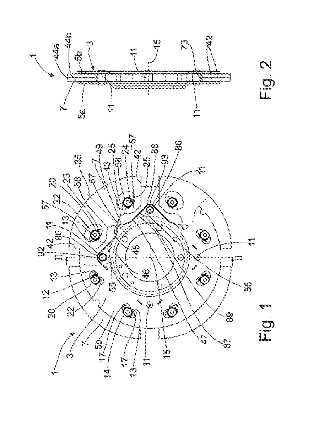
[0035]FIG. 1 shows a mass damper system 1 with a damper mass carrier 3 that has two axially spaced damper mass support elements 5a, 5b, of which only the damper mass support element 5b arranged axially in front of the damper masses 7 in viewing direction is shown for the sake of a clearer illustration of the subject matter of the invention. The two damper mass support elements 5a, 5b are connected to one another by spacer pieces 11. The two damper mass support elements 5a, 5b and spacer pieces 11 are shown in FIG. 2, which is a view along section line II-II in FIG. 1. FIG. 2 also conveys particulars about the damper masses 7, which have a plurality of damper mass elements 44a, 44b in axial direction. The circumferential sides 42 on both sides of the damper masses 7 adjoin a radially inner stop side 43. The stop side 43 of the respective damper mass 7 is profiled and has in the area of a damper mass center 35 a radial projection 57 adjoined at both sides in circumferential direction ...


PUM


Abstract

A mass damper system is provided with a damper mass carrier with at least one damper mass movable relative to the damper mass carrier and at least one stop. The damper mass moves within a predetermined movement region when a rotational movement of the damper mass carrier exceeds a predetermined limit speed. The predetermined movement region has a first movement region portion bounded at one end by an initial position in which the damper mass is free from a deflection in circumferential direction and by a limit position in which the damper mass has undergone a deflection, and a second movement region portion is defined at one end by the limit position and at the other end by a stop position in which the damper mass has come in contact with the stop.

Description

CROSS REFERENCE TO RELATED APPLICATIONS[0001]This is a U.S. national stage of application No. PCT / EP2014 / 066300, filed on Jul. 29, 2014. Priority is claimed on German Application No.: DE102013217089.0, Filed Aug. 28, 2013, the content of which is incorporated herein by reference.BACKGROUND OF THE INVENTION[0002]1. Field of the Invention[0003]The present invention is directed to a mass damper system with a damper mass carrier at which is received at least one damper mass movable relative to the damper mass carrier and at least one stop. The damper mass moves within a predetermined movement region at least during an operating state in which a rotational movement of the damper mass carrier around a central axis has exceeded a predetermined limit speed.[0004]2. Detailed Description of the Prior Art[0005]A mass damper system of the type mentioned above is known from DE 10 2009 042 818 A1. The mass damper system has in the radially inner region an annular component part which, like a hub ...

Claims


Application Information

Patent Timeline
Patent Type & Authority Patents(United States)
IPC IPC(8): F16F15/14F16H45/02
CPCF16F15/145F16H45/02F16H2045/0263F16H2045/0226
Inventor SIEMENS, KYRILLSUDAU, JORG
Owner ZF FRIEDRICHSHAFEN AG
Why Eureka
Try Eureka