

Flywheel structure of engine and engine
A technology for engines and flywheels, applied to flywheels, mechanical equipment, vibration suppression adjustments, etc., can solve problems such as knocking noise in the car, and achieve the effects of reducing stiffness, avoiding knocking noise, and reducing inertia
- Summary
- Abstract
- Description
- Claims
- Application Information
AI Technical Summary
Problems solved by technology
Method used
Image

Examples
Embodiment Construction
[0030] Embodiments of the present invention are described in detail below, examples of which are shown in the drawings, wherein the same or similar reference numerals designate the same or similar elements or elements having the same or similar functions throughout. The embodiments described below by referring to the figures are exemplary and are intended to explain the present invention and should not be construed as limiting the present invention.
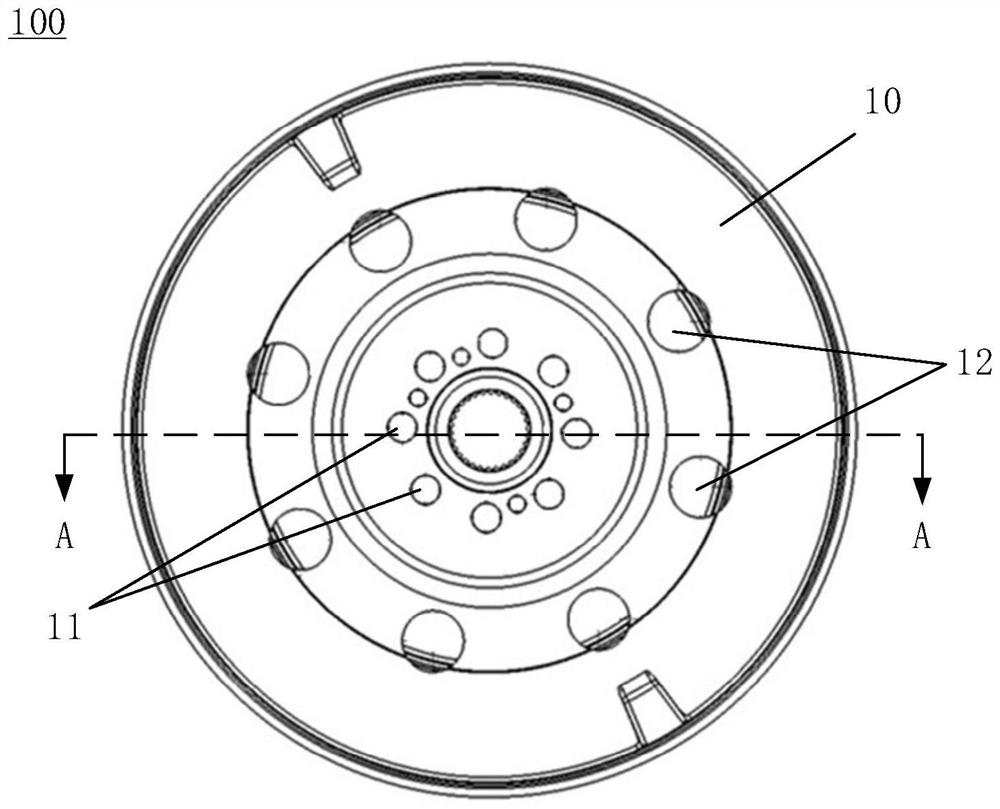
[0031] figure 1 is a schematic front view of a flywheel structure 100 of an engine according to an embodiment of the present invention. Such as figure 1 As shown, in a specific embodiment, the flywheel structure 100 of the engine includes a flywheel front cover 10, and the flywheel front cover 10 is provided with at least one set of bolt holes 11 for connecting with the engine crankshaft (not shown in the figure) and using At least one group of through holes 12 for reducing the stiffness of the flywheel structure 100, wherein e...
PUM
 Abstract
Description
Claims
Application Information