Vane pump having vanes slanted relative to rotational axis

a technology of slanting vanes and vane pumps, applied in the field of vane pumps, can solve the problems of generating hitting noise, complex vane pumps, and high cost, and achieve the effect of preventing hitting nois

Inactive Publication Date: 2007-06-05
DENSO CORP
View PDF6 Cites 2 Cited by
  • Summary
  • Abstract
  • Description
  • Claims
  • Application Information

AI Technical Summary

Benefits of technology

[0007]The present invention has been made in view of the above-mentioned problem, and an object of the present invention is to provide an improved vane pump, in which the hitting noises are prevented without using additional members such as resilient rings.
[0010]Since the vane is pushed upward against the upper plate according to rotation of the rotor, the vane does not move in the axial direction. That is, the vane does not hit the upper plate while the rotor is being rotated, and therefore the hitting noises are prevented without using any other additional component to restrict movement of the vane. A cross-section of the vane taken along a plane parallel to the rotational axis is made in a parallelogram shape, so that the upper end surface of the vane contacts the upper plate with a surface-to-surface relation. This suppresses abrasion wear of the vane and the upper plate.
[0011]The slanting direction of the groove may be reversed, so that the lower end of the groove is positioned backward of the rotational direction. In this case, the lower surface of the vane is pushed against the lower plate according to rotation of the rotor, thereby suppressing the hitting noises between the vane and the lower plate. The vane pump of the present invention may be used in a system for checking leakage in a fuel evaporation control system mounted on an automotive vehicle. Since a pump for sucking air in a fuel tank is driven when an engine is not operated, it is important to use a pump generating low noises. Since the vane pump of the present invention generates low noises, it can be advantageously applied to the system for checking leakage.

Problems solved by technology

Accordingly, the vane moves also in the axial direction according to rotation of the rotor and tends to hit the casing, generating hitting noises.
In the proposed vane pump, however, it is necessary to provide the resilient rings that make the vane pump complex and expensive.

Method used


Image

  • Vane pump having vanes slanted relative to rotational axis
  • Vane pump having vanes slanted relative to rotational axis
  • Vane pump having vanes slanted relative to rotational axis

Examples


Embodiment Construction

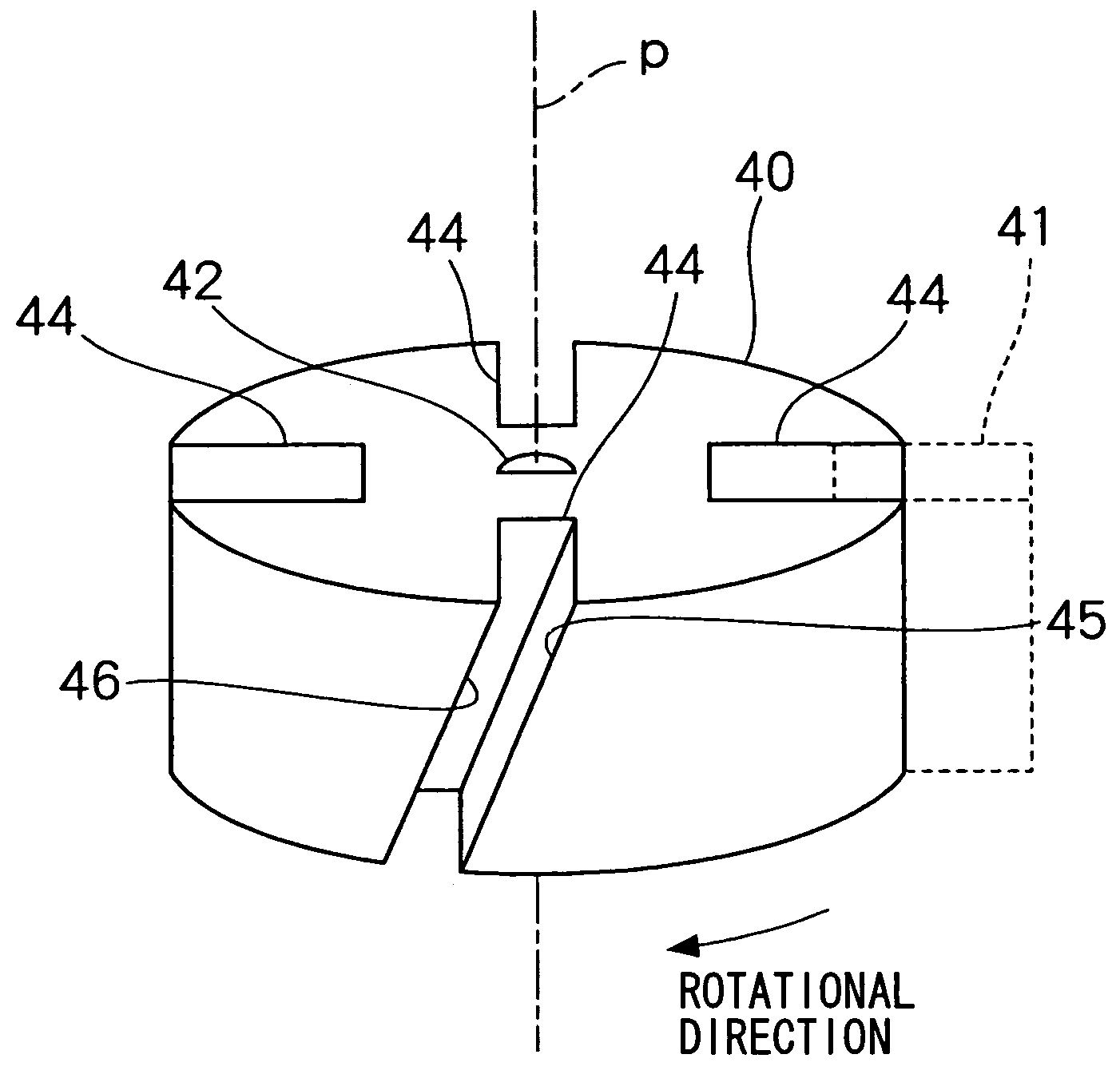
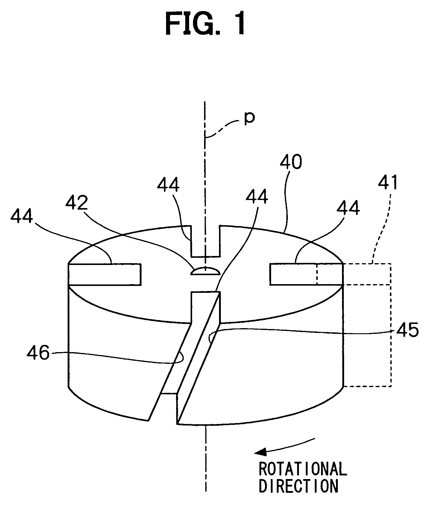
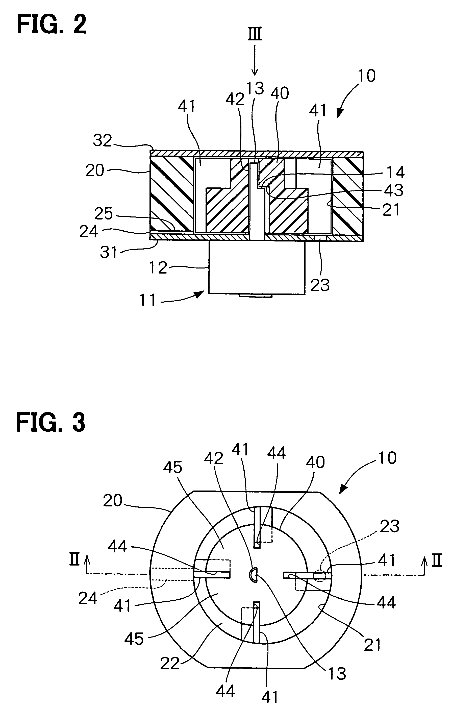
[0019]A preferred embodiment of the present invention will be described with reference to FIGS. 1-4. First, referring to FIGS. 2 and 3, a structure of a vane pump 10 will be described. The vane pump compresses or decompresses fluid such as gas or liquid. The vane pump 10 includes: a casing composed of a ring 20, a lower plate 31 and an upper plate 32; a rotor 40; vanes 41 and a driving shaft 13. The rotor 40 disposed in an inner bore 21 of the ring 20 is coupled to the driving shaft 13 and rotated by a motor 11. The motor 11 may be an electric motor such as a direct current motor or an alternating current motor. The motor 11 is contained in a cover 12.

[0020]The ring 20 is cylinder-shaped and has a cylindrical inner bore 21. The inner bore 21 may be formed in an oval form. Both axial ends of the ring 20 are closed with the lower plate 31 and the upper plate 32. A rotational axis of the rotor 40 disposed in the inner bore 21 is positioned in an eccentric relation with respect to a cen...


PUM


Abstract

A vane pump is composed of a casing having a cylindrical inner bore and a rotor disposed in the inner bore with an eccentric relation to the inner bore. A circular pump chamber formed between the rotor and the inner bore is divided by vanes disposed in the rotor into plural pump chambers each changing its capacity according to rotation of the rotor. The vane is slidably disposed in a groove formed in the rotor in a slanted relation with respect to a rotational axis of the rotor. When the rotor rotates, the vane is pushed backward of the rotational direction by fluid in the pump chamber. The pushing force includes a component for pushing the vane upward toward an upper plate closing an upper opening of the inner bore. The vane is pushed against the upper plate to thereby prevent hitting noises between the vane and the upper plate.

Description

CROSS-REFERENCE TO RELATED APPLICATION[0001]This application is based upon and claims benefit of priority of Japanese Patent Application No. 2004-321986 filed on Nov. 5, 2004, the content of which is incorporated herein by reference.BACKGROUND OF THE INVENTION[0002]1. Field of the Invention[0003]The present invention relates to a vane pump for compressing or decompressing fluid.[0004]2. Description of Related Art[0005]A vane pump having a rotor rotating in an eccentric relation with respect to an inner bore of a casing is known hitherto. The vane pump has vanes disposed in grooves formed in the rotor to extend in the axial direction. The vanes move in the radial direction according to rotation of the rotor so that radial ends of the vanes slidably contact the inner bore of the casing. An axial length of the vane is made a little smaller than an axial length of the groove to allow its smooth movement in the groove. In other words, small gaps are formed between the vane and casing. Ac...

Claims


Application Information

Patent Timeline
Patent Type & Authority Patents(United States)
IPC IPC(8): F01C1/00F03C2/00
CPCF01C21/0809F04C2/3442F04C18/3442
Inventor KATO, YASUOYAMADA, YOSHICHIKA
Owner DENSO CORP
Why Eureka
Try Eureka