Swivel motor

a technology of swivel motors and swivel springs, which is applied in the direction of servomotors, machines/engines, engines without rotary main shafts, etc., can solve the problems of high manufacturing cost and achieve the effect of preventing the noise of impact and preventing the resulting destruction of elastomer springs

Inactive Publication Date: 2011-08-23
ZF FRIEDRICHSHAFEN AG
View PDF7 Cites 2 Cited by
  • Summary
  • Abstract
  • Description
  • Claims
  • Application Information

AI Technical Summary

Benefits of technology

It is an object of the present invention to prevent the impact noise at a slide element in a swivel motor actuated by a pressure medium and, in so doing, to prevent the resulting destruction of the elastomer springs.
An advantage is that the volume compensation space is formed by a neck in the profile of the elastomer spring. Generally, the installation space for the elastomer spring could also be profiled, but the manufacturing cost would be very high. In an elastomer spring produced by injection molding, profiling can be implemented in a very simple manner.
A fastening groove having at least one groove side surface extending conically with respect to the center axis of the pressure compensation element is provided for fixing the elastomer spring. Apart from the especially simple fixing of the elastomer spring, another effect is achieved in that pressure medium can flow in between the elastomer springs and the fastening groove and can be pressed out via the volume compensation spaces during a compression of the elastomer springs so that a hydraulic pressure force is developed which additionally dampens the movement of the pressure compensation element.

Problems solved by technology

Generally, the installation space for the elastomer spring could also be profiled, but the manufacturing cost would be very high.

Method used


Image

  • Swivel motor
  • Swivel motor
  • Swivel motor

Examples


Embodiment Construction

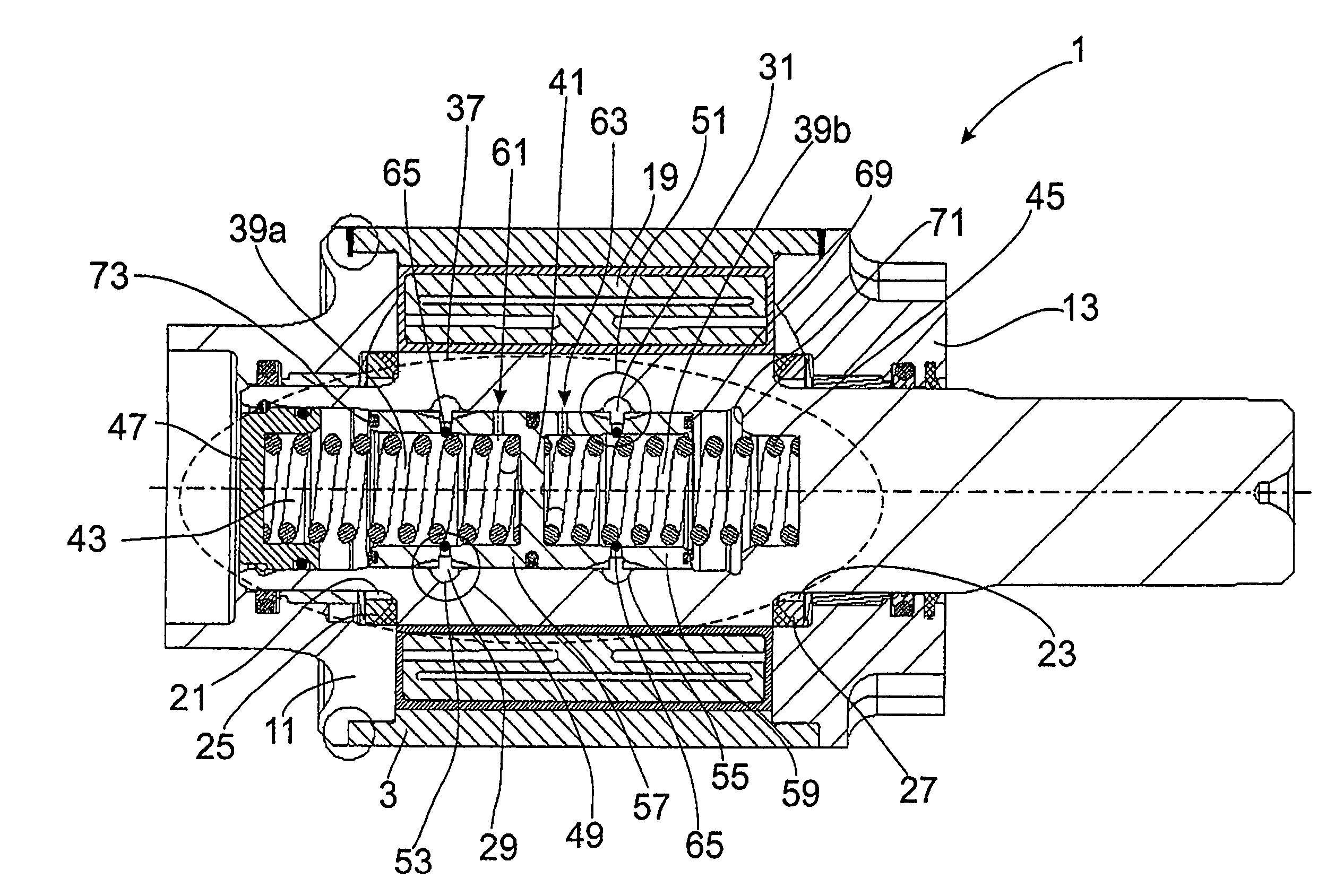
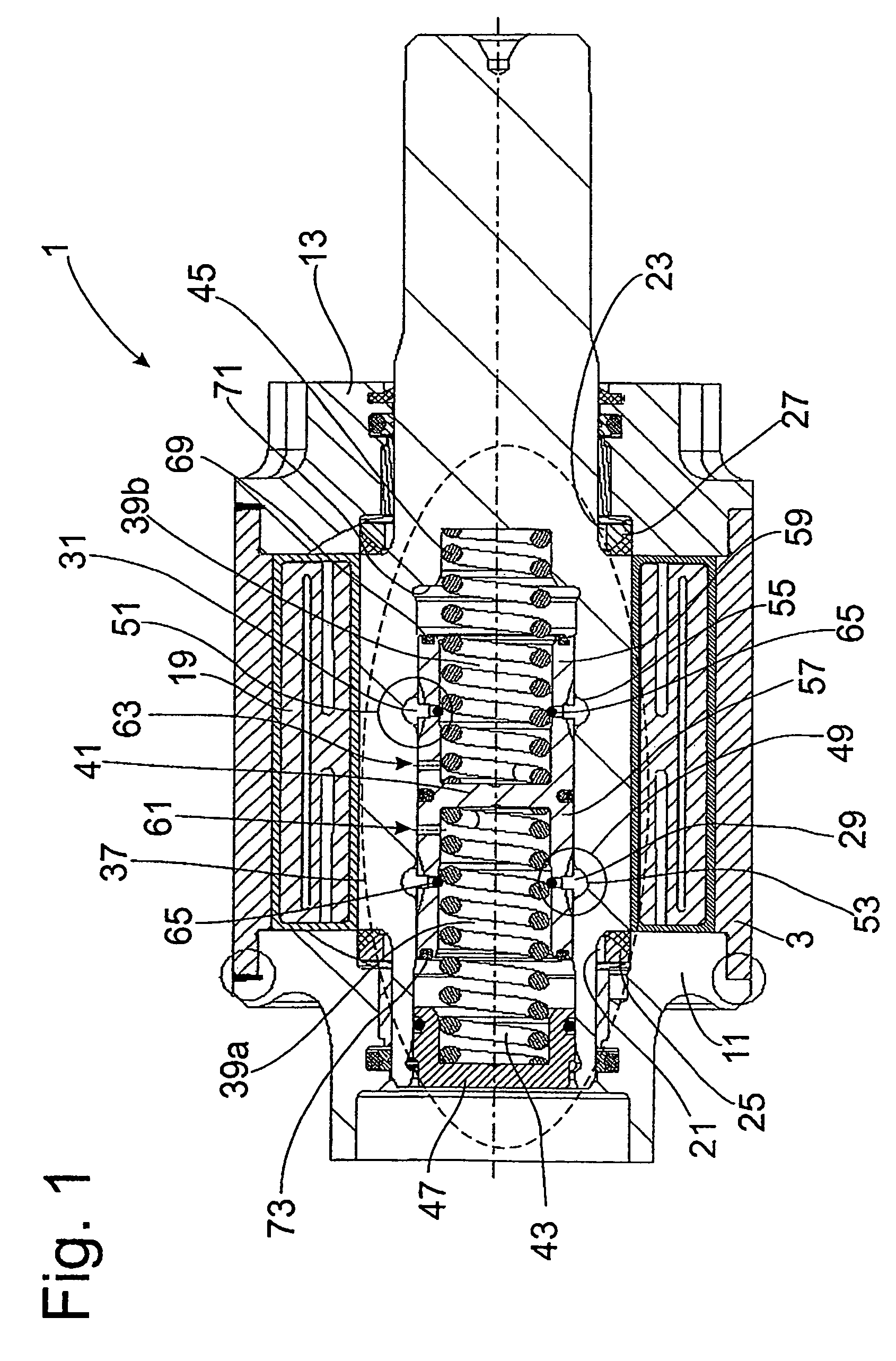
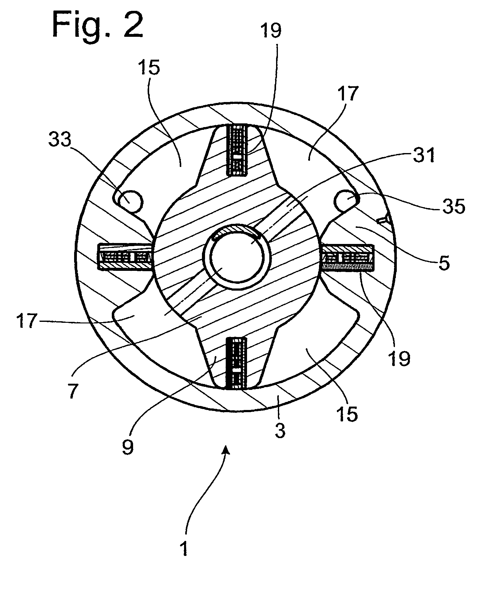
FIG. 1, in connection with FIG. 2, shows a swivel motor 1 in longitudinal section. This basic construction is also assumed in the following drawings. The swivel motor 1 comprises a cylinder 3, axially extending ribs 5 being formed at its inner diameter. A motor shaft 7 is supported inside the cylinder 3 so as to be rotatable. Vanes 9 extending parallel to the ribs 5 are arranged on the motor shaft. The cylinder 3 is closed by covers 11 and 13 at the ends. The motor shaft 7 with its vanes 9 and the cylinder 3 with its ribs 5 together with the covers 11 and 13 form work chambers 15 and 17 which are separated from one another by disk seals 19 in the vanes and ribs. Further, shaft seals 25 and 27 are arranged in the annular spaces 21 and 23 of the covers 11 and 13 and prevent pressure medium from exiting the work chambers 15 and 17. Between the work chambers 15 and 17, there is a join system comprising channels 29 and 31 in the motor shaft 7. A first pressure medium connection 33 suppli...


PUM


Abstract

A swivel motor has a plurality of work chambers and a join system between the work chambers that joins the work chambers at least by pairs. The arrangement of the joined work chambers is carried out in such a way that the work chambers which are connected to the first pressure medium connection alternate with those which are connected to the second pressure medium connection. At least two work chambers associated with different pressure medium connections are connected to a pressure compensation element, and the pressure compensation element is formed by a compensation space that is divided by a movable dividing element. A partial compensation space is connected in each instance to at least one work chamber of a pressure medium connection, and the dividing element is held in an initial position by oppositely acting springs. The spring force characteristic is formed by a spring arrangement which comprises a plurality of springs and has at least one coil spring and one elastomer spring. At least one volume compensation space is available for the elastomer spring.

Description

BACKGROUND OF THE INVENTION1. Field of the InventionThe invention relates to a swivel motor and particularly to a unit actuated by pressure medium.2. Description of the Related ArtPressure medium-actuated units are generally used to support a structural component part in an operating movement. In such cases, the structural component part can be subject to an external load. In a unit that is constructed as a swivel motor, in a vehicle chassis, a stabilizer arrangement can execute a swiveling movement but, due to deflection of the wheels of one axle, the swivel motor is exposed to a load of an appreciably higher frequency than the rocking movement of a vehicle body pressure changes in the pressure-medium supply.In DE 10 2004 051 444 A1 pulsing of the pressure medium is discussed and by way of a solution a foam body is arranged in at least one work chamber of the unit. The foam body has at least one disadvantage in that the operating path of the unit is restricted. Further, it must be ...

Claims


Application Information

Patent Timeline
Patent Type & Authority Patents(United States)
IPC IPC(8): F15B15/12F16L55/04
CPCF15B15/12
Inventor BOTTGER, CHRISTIAN
Owner ZF FRIEDRICHSHAFEN AG
Why Eureka
Try Eureka