Wireless smart battery system

a battery system and wireless technology, applied in secondary cells, electrochemical generators, instruments, etc., can solve problems such as system failure to report or otherwise communicate battery status, device unexpected shutdown, and prevent the use of smart battery features on devices that do no

Active Publication Date: 2019-02-05
KANAREK ROSS
View PDF13 Cites 3 Cited by
  • Summary
  • Abstract
  • Description
  • Claims
  • Application Information

AI Technical Summary

Benefits of technology

[0007]The current invention is a wireless smart battery communication system, incorporating a processor, a connector complying with a smart battery management standard and a wireless communication system. The wireless smart battery connector allows a user to view the status of one or more smart batteries using a wireless device. Multiple smart battery communication systems, each connected to and / or incorporating one smart battery, may be connected to a single wireless device. The preferred embodiment of the invention is a smart battery connector incorporated into a battery mount plate that connects a device and a smart battery. The current invention allows a user to remotely and wirelessly monitor and manage multiple smart batteries powering multiple devices and / or being recharged in devices or dedicated charging devices.

Problems solved by technology

In an environment, however, where the device powered by the battery is not directly attended by a user or where a user is using multiple battery-powered devices at once, this can result in a device unexpectedly shutting off as its battery runs out of power.
Additionally, it prevents the use of smart battery features on devices that do not incorporate computer processors and / or displays.
Current smart battery features and systems cannot report or otherwise communicate battery status to device other than a device the battery is connected to by a wired connection.
Further, multiple smart batteries or smart battery systems do not aggregate the statuses of their batteries or offer an interface where a user can review the status of multiple batteries at once.
This can be a problem in a workplace or other setting where multiple devices, each powered by one or more rechargeable batteries, are all continuously or intermittently operating, and the loss of power to one device can interrupt work or other tasks.
Additionally, devices that do not implement fully-featured smart battery communication systems may only communicate particular attributes, such as voltage or amperage, via an analogue port or connector.

Method used


Image

  • Wireless smart battery system
  • Wireless smart battery system
  • Wireless smart battery system

Examples


Embodiment Construction

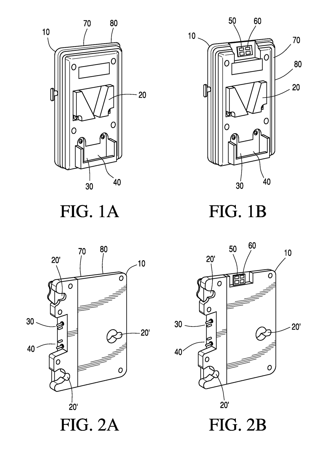
[0030]In a first embodiment, as depicted in FIGS. 1A, 1B, 2A and 2B, the present invention comprises a mount plate housing 10, a battery attachment mount 20, a battery power terminal 30, a battery communication terminal 40, a wireless communication systems 50, a processor 60, a device power terminal 70 and a device communication terminal 80. The mount plate housing 10 is of similar size, shape and design to the battery mount plates known to those skilled in the relevant art and used in the audiovisual recording industry. The battery attachment mount 20 may be an industry-standard V-mount 20 as shown in FIG. 1A and FIG. 1B, a 3-stud mount 20′ as shown in FIG. 2A and FIG. 2B or any other system or mechanism for attaching a battery to a mount plate. The battery power terminal 30 is located and configured as standard for the type of battery attachment mount 20 used. The battery power terminal 30 is a plurality of connectors such as, without restriction, prongs, contacts or sockets that ...


PUM

PropertyMeasurementUnit
poweraaaaaaaaaa
timeaaaaaaaaaa
output voltageaaaaaaaaaa

Abstract

A wireless system for monitoring rechargeable and single-use batteries. The wireless system is usable with existing batteries that implement a smart battery standard and / or an analog port. The wireless system may be installed in the battery, in a battery-powered device, in a battery mount plate, in an attachment that connects to an analog port and / or in a battery charging station or charging device. The wireless system transmits the battery's status to a remote user device, which may be a tablet, smartphone or other wireless device. The system allows a user to monitor one or more batteries remotely.

Description

FIELD OF THE INVENTION[0001]The present invention relates to rechargeable battery systems such as those used for electronic devices including, without restriction, cameras, computers, medical and audiovisual equipment.[0002]The present invention is a wireless communication system for batteries and battery-powered systems that includes a network connection element that transmits information regarding the battery to one or more electronic devices. The present invention may be integrated into the battery, integrated into an electronic device powered by a battery or may be an attachment for such an electronic device that interoperates with the battery powering the device.BACKGROUND OF THE INVENTION[0003]Many devices, including computers, cameras, lights, phones, radios and other equipment, use rechargeable batteries for power. These batteries typically attach to the device by mechanical latches or connections. In particular, in many items of audiovisual recording equipment, a rechargeab...

Claims


Application Information

Patent Timeline
Patent Type & Authority Patents(United States)
IPC IPC(8): H02J7/00G01R31/36H01M10/48H01M10/42
CPCG01R31/3648H01M10/4257H02J7/0045H01M10/48H02J2007/0098H02J2007/0096G01R31/371G08C17/02H02J7/00034Y02E60/10
Inventor KANAREK, ROSS
Owner KANAREK ROSS
Why Eureka
Try Eureka