Lid with hidden stacking

Active Publication Date: 2019-02-12
PLASTIC INGENUITY
View PDF6 Cites 1 Cited by
  • Summary
  • Abstract
  • Description
  • Claims
  • Application Information

AI Technical Summary

Benefits of technology

[0008]Compared to the prior art which uses convex external protrusions or lugs to provide stacking separation, a lid according to my invention can provide stacking separation without the use of structures that are readily apparent to the end consumer, thereby enhancing the aesthetics, general smoothness, and uniform appearance of products comprising the lid. Although there are still differences between different units of the same product, with my lid those differences are relatively subtle and much less noticeable.
[0009]A lid according to my invention can also achieve a greater maximum vertical separation distance. The prior art lids discussed below use convex external protrusions or lugs along with a second structure, a lower side wall and periphery, to provide stacking separation. The overall height of the prior art lid is the lug height (the stacking separation) plus the height of that second structure, so the stacking separation has to be less than the total vertical height. In contrast, a lid according to my invention can theoretically provide stacking separation almost the entire vertical height of the lid, by making the channel, trench, or valley depth equa

Problems solved by technology

This level of engagement between adjacent lids can be problematic because the lids are made of relatively soft and hot plastic (having been just thermoformed at high temperature).
If the lids stick together, that can cause manufacturing problems such as line stoppages and/or scrap.
However, too much space between adjacent lids can reduce

Method used


Image

  • Lid with hidden stacking
  • Lid with hidden stacking
  • Lid with hidden stacking

Examples


Example

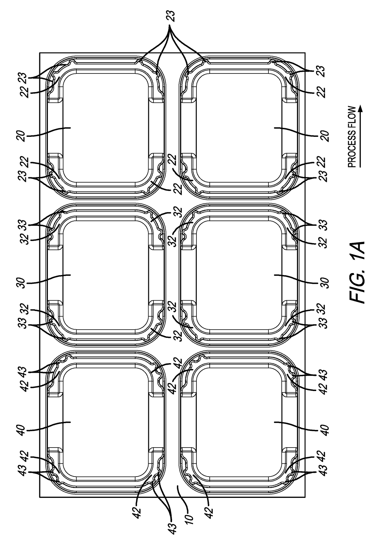
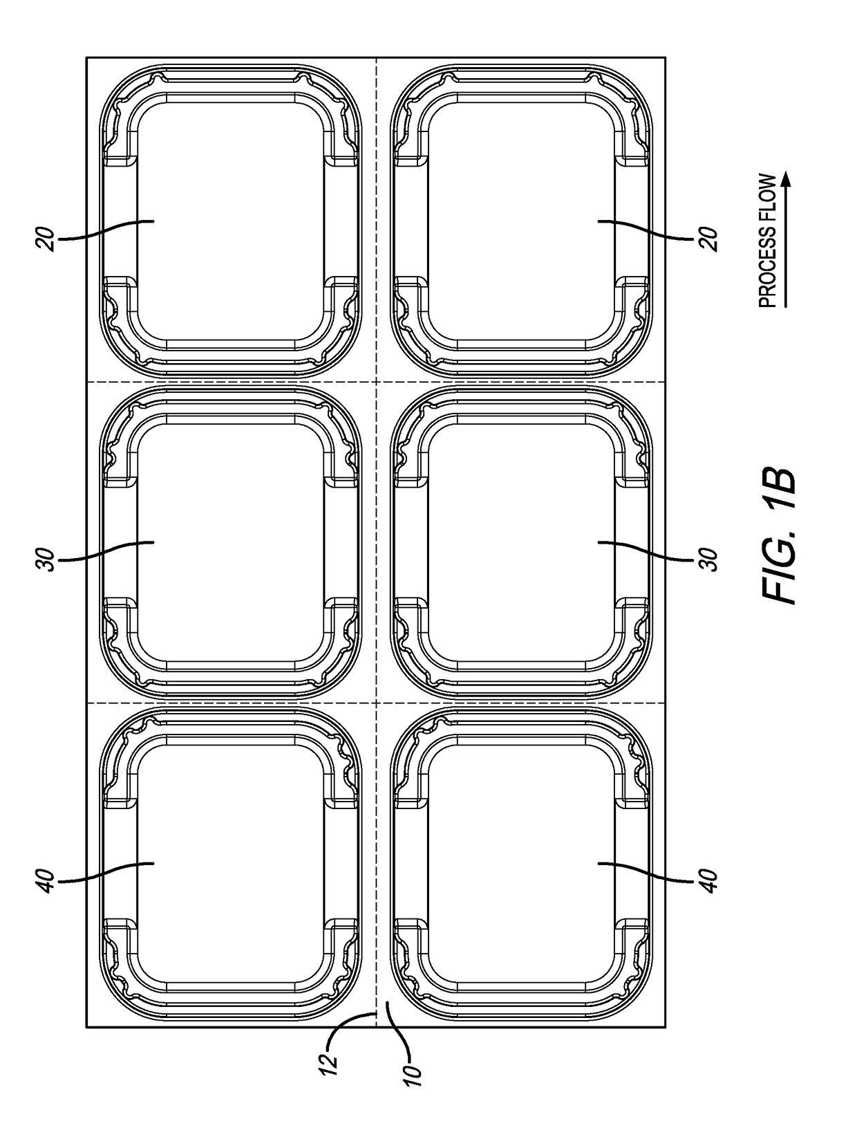
[0033]FIGS. 1A-1B provide plan views of a portion of a prior art sheet 10 of thermoformed lids 20, 30&40, with FIG. 1B the same as FIG. 1A except for dotted lines added to show the approximate locations of the cuts 12 used to separate the individual lids 20, 30, &40. As this portion of a prior art sheet 10 moves in the direction of process flow shown in FIGS. 1A & 1B, after the parts come off the line they will ordinarily form a stack 14 on top of one another with lid 20 on the bottom, followed by lid 30 in the middle, and lid 40 on top as shown in FIGS. 3A-3B.

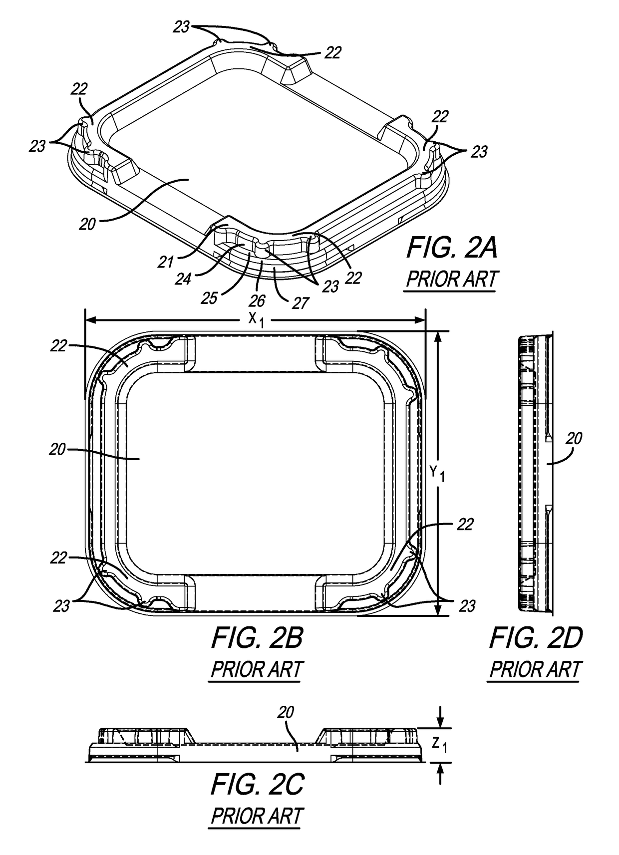
[0034]As shown in FIGS. 2A-2D, the first prior art lid 20 has an upper periphery 21 with four stacking areas 22 located at the corners. Each stacking area 22 has a convex protrusion or lug 23 that juts or projects outwardly from an upper side wall 24. On each lateral side of the outward-projecting lug 23 is a shelf 25 which extends to a corner 26 and to a lower side wall and periphery 27.

[0035]Similarly, as shown in FIGS. 2E-2...


PUM


Abstract

A kit of thermoformed lids comprising a three lids which are substantially similar except for specific differences in four stacking areas located at the corners of the lids. Unlike prior art lids that use convex external lugs to provide separation during stacking, lids according to the present invention have stacking areas formed as interruptions in concave channels located along the peripheries of the lids, improving the appearance and uniformity of products comprising the lids.

Description

FIELD OF THE INVENTION[0001]This invention relates generally to the field of thermoformed objects and containers. More particularly, the present invention relates to thermoformed lids having features that enhance stacking, separability, and uniformity when multiple lids are nested and stacked together.BACKGROUND OF THE INVENTION[0002]Thermoformed plastic containers are well known as inexpensive and highly customizable containers for the sale of a wide variety of products, everything from cell phones to deli meats. Thermoformed plastic containers are typically transparent and rigid, so they can give a consumer the ability to examine a product closely. They can be made tamper-resistant, to reduce the risk that the product could be damaged or contaminated. They are typically lightweight, and can be manufactured in a wide variety of shapes for different uses, such as cups, plates, deli trays, or as lids or covers for any of these common shapes.[0003]Thermoformed plastic objects, such as...

Claims


Application Information

Patent Timeline
IPC IPC(8): B65D51/24B65D21/02B65D43/02
CPCB65D51/24B65D43/02B65D21/0217B65D2543/00027
Inventor SCHULTZ, JOSEPH L.
Owner PLASTIC INGENUITY
Why Eureka
Try Eureka