Fusible member intended to join two yokes to form a hinge

a technology of a member and a hinge, which is applied in the direction of pivotal connections, mechanical devices, transportation and packaging, etc., can solve the problems of limited fatigue strength and need to be changed too often

Active Publication Date: 2019-02-19
SAFRAN LANDING SYSTEMS
View PDF9 Cites 0 Cited by
  • Summary
  • Abstract
  • Description
  • Claims
  • Application Information

AI Technical Summary

Benefits of technology

[0012]The object of the invention is to propose a design solution that makes it possible to reconcile the fatigue strength and rupture threshold constraints for such a fusible member.

Problems solved by technology

Since the constraints concerning fatigue strength and rupture above a certain load threshold are difficult to reconcile, that leads to designing a fusible member with limited fatigue strength, which implies that it needs to be changed too frequently.

Method used


Image

  • Fusible member intended to join two yokes to form a hinge
  • Fusible member intended to join two yokes to form a hinge
  • Fusible member intended to join two yokes to form a hinge

Examples


Embodiment Construction

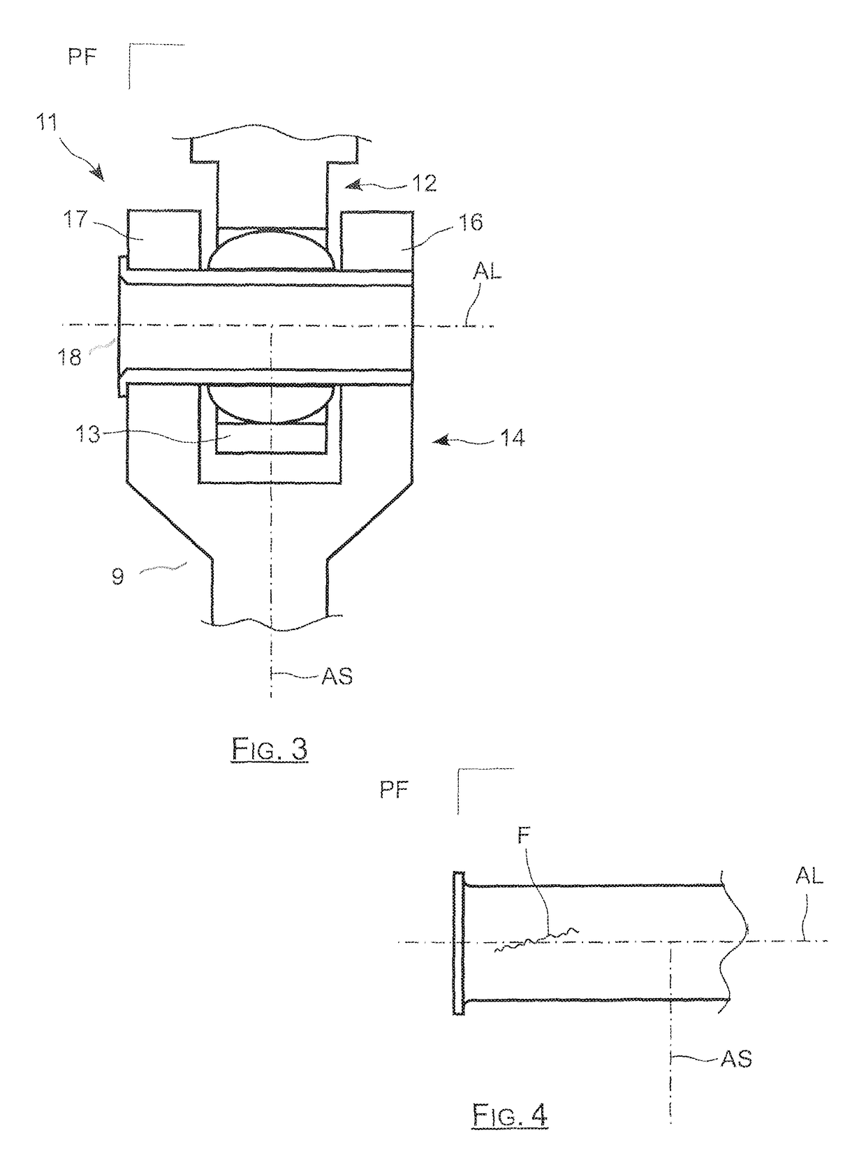
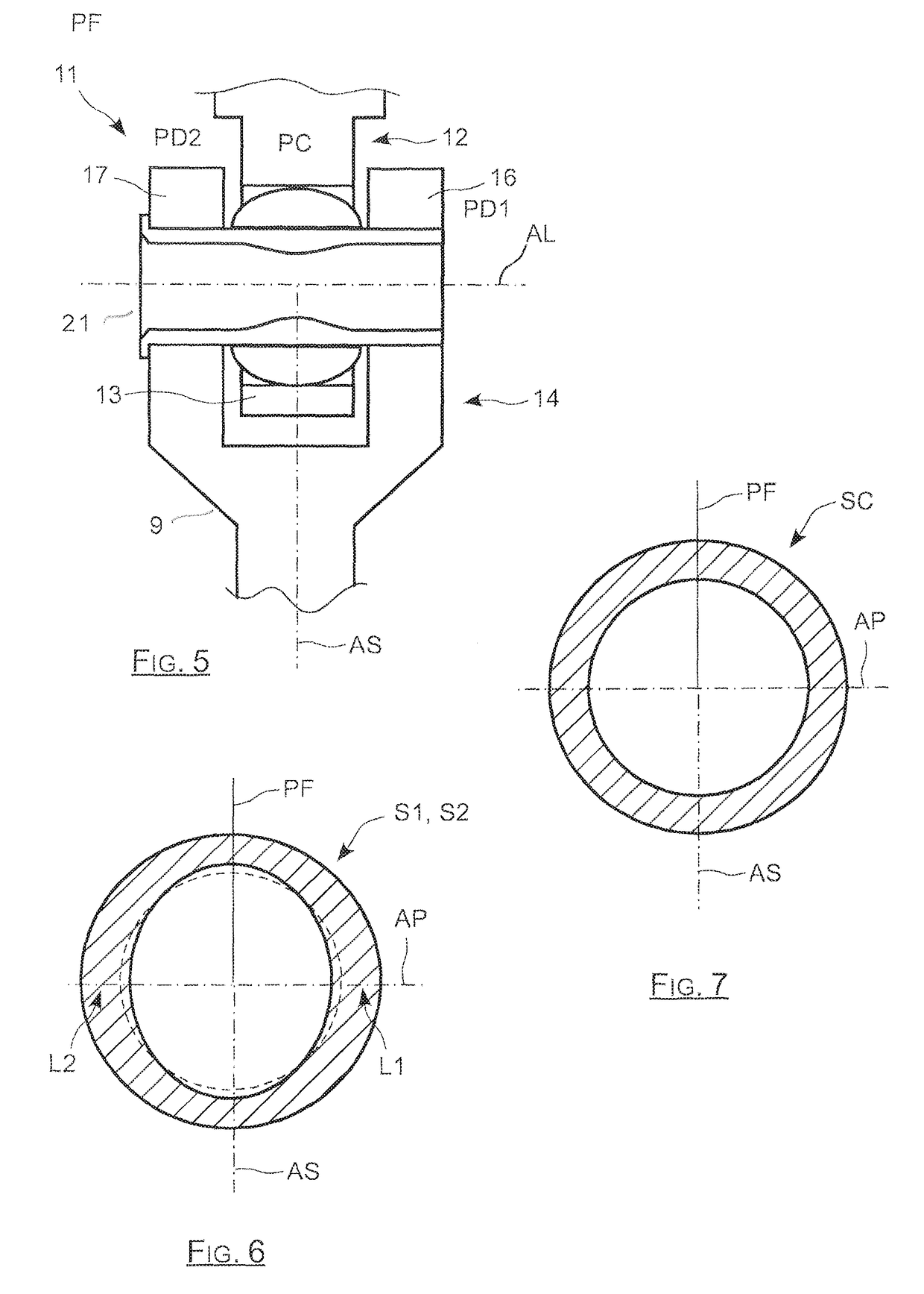
[0029]The idea on which the invention is based lies in the observation that when the prior art fusible member is correctly dimensioned with respect to its rupture force threshold, and when it is mounted so as to be prevented from rotating, then premature rupture in fatigue gives rise to one or more rupture starters that always appear in the same regions of the fusible member.

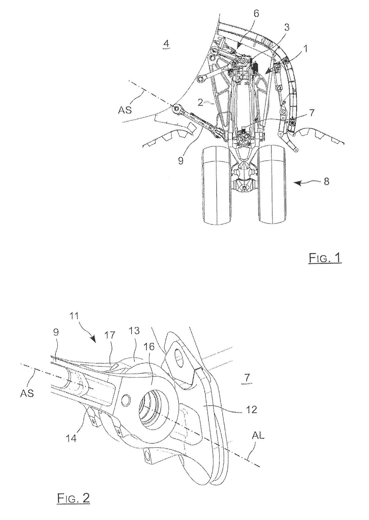
[0030]As shown in FIG. 3, which is a cross-section view of the connection 11 of FIGS. 1 and 2, the forces to which the fusible member 18 are subjected on each landing are always directed in the same manner, such that the fusible member 18 is stressed in the same manner on each occasion.

[0031]The fusible member 18 is subjected to the operating force that is directed parallel to the axis AS and comprises two components that are applied respectively to the lugs 16 and 17 of the clevis 14, and the reaction from the single lug 13 of the clevis 12. In other words, all of the forces to which the fusible member are subj...


PUM


Abstract

The invention relates to a tubular fusible member (21) extending along a longitudinal axis (AL) and for engaging in a two-lug clevis (14) and a single-lug clevis (12) in order to form a hinge (11). According to the invention, the fusible member (21) is constrained in rotation with one of the clevises (12, 14), and it presents a cross-section of shape that varies gradually between a central section and two distal sections, each distal section having reinforced thickness in its regions that extend parallel to the bending plane (PF) in which the fusible member (21) bends when it is stressed, the central section having a second moment of area relative to an axis normal to the bending plane (PF) that is greater than the second moment of area of the distal sections.

Description

CROSS REFERENCE TO RELATED APPLICATIONS[0001]This application is a National Stage of International Application No. PCT / EP2014 / 050385 filed Jan. 10, 2014, claiming priority based on French Patent Application No. 13 50205 filed Jan. 10, 2013, the contents of all of which are incorporated herein by reference in their entirety.[0002]The invention relates to connecting together two mechanical elements fitted respectively with a two-lug clevis and with a single-lug clevis that is secured to the two-lug clevis by a fusible member of the type comprising a tubular or solid mechanical pin.BACKGROUND OF THE INVENTION[0003]Such a connection is typically to be found in the components of retractable aircraft landing gear, such as the landing gear 1 shown deployed in FIG. 1. Such landing gear comprises a leg 2 having a top end 3 secured to a structural element 4 of the aircraft by means of a set of hinged top links 6. The bottom end 7 of the leg 2 carries a wheel set 8 and is secured to the struct...

Claims


Application Information

Patent Timeline
Patent Type & Authority Patents(United States)
IPC IPC(8): F16C11/04B64C25/00F16C11/06B64D45/00
CPCF16C11/045B64C25/00F16C11/0614Y10T403/32221B64D2045/008
Inventor ANTONI, NICOLAS
Owner SAFRAN LANDING SYSTEMS
Why Eureka
Try Eureka