Trajectory-based sensor planning

a technology of trajectory-based sensors and planning, applied in the direction of process and machine control, using reradiation, instruments, etc., can solve the problems of limiting the ability to navigate the vehicle autonomously, inability to view laterally, poor peripheral perception,

Active Publication Date: 2019-03-12
SIKORSKY AIRCRAFT CORP
View PDF16 Cites 0 Cited by
  • Summary
  • Abstract
  • Description
  • Claims
  • Application Information

AI Technical Summary

Problems solved by technology

For directional sensors of a perception system that have a substantially limited field of view, a straight-ahead view typically spans large distances but peripheral perception can be poor.
Inability to view laterally can limit the ability to navigate the vehicle autonomously in obstacle-rich environments, especially with aggressive flight paths that involve sharp turns.
Additional sensors can be added to enhance a peripheral field of view, but this also adds weight and cost to the vehicle.

Method used


Image

  • Trajectory-based sensor planning
  • Trajectory-based sensor planning
  • Trajectory-based sensor planning

Examples


Embodiment Construction

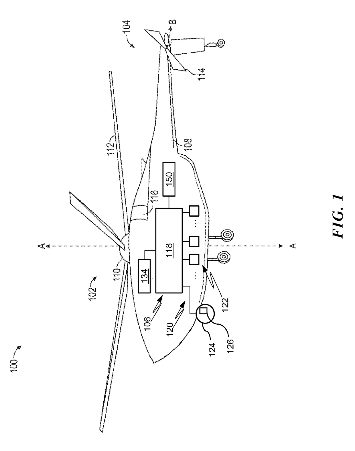
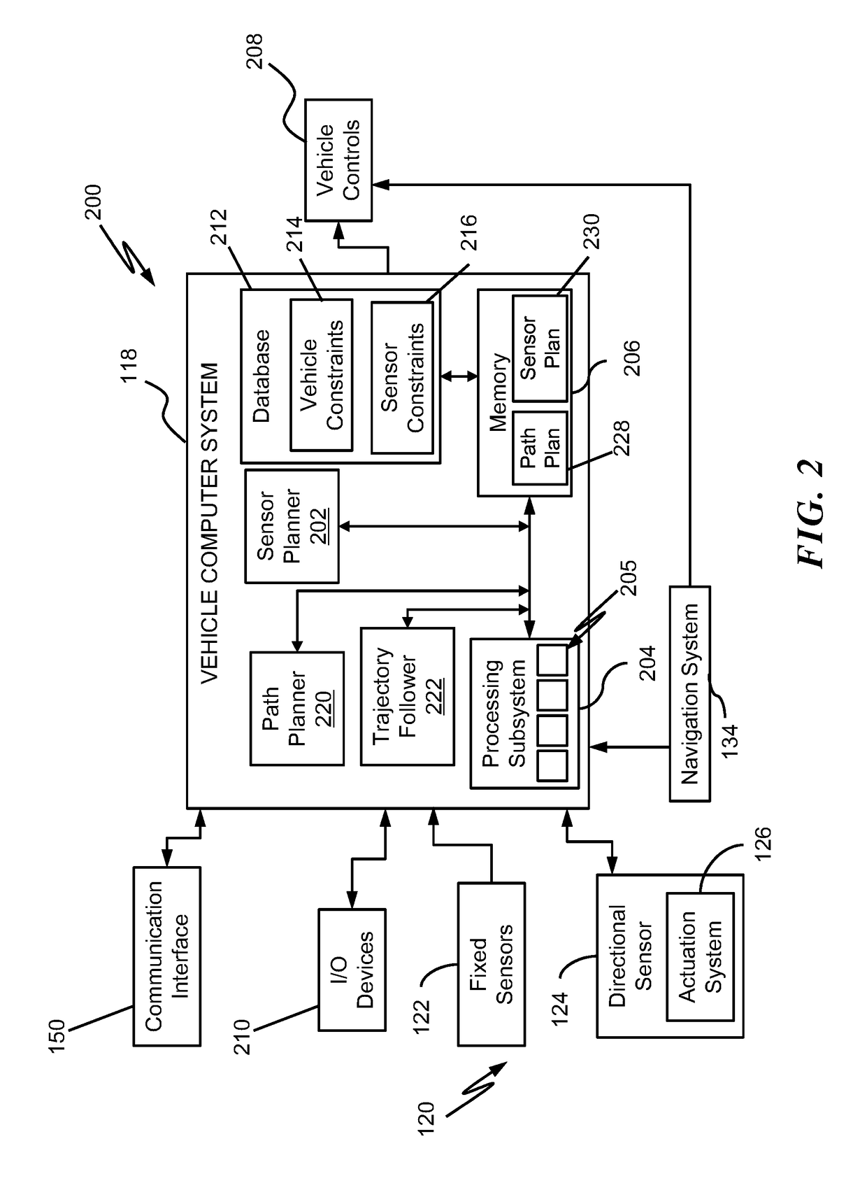
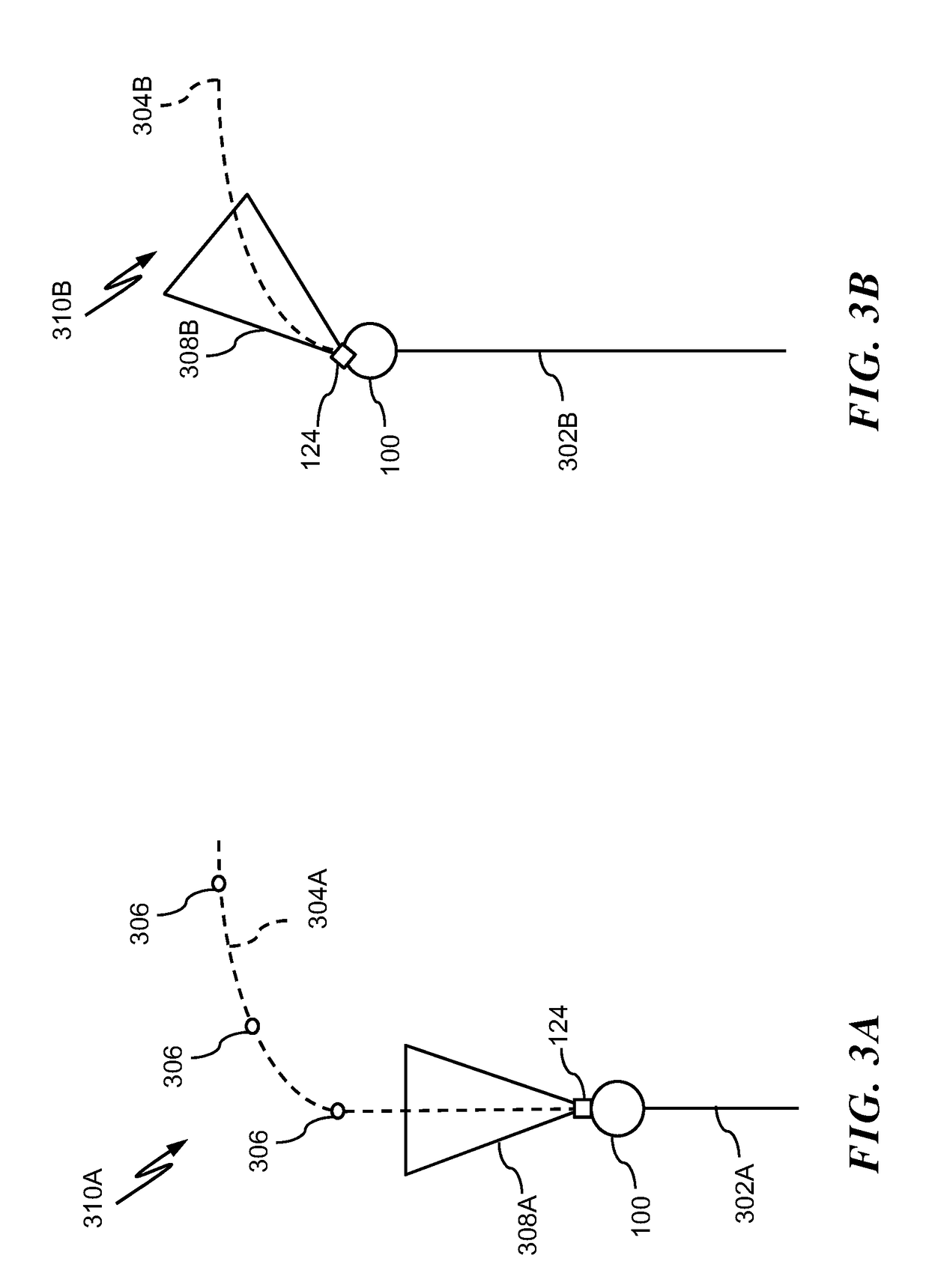
[0017]In exemplary embodiments, trajectory-based sensor planning on a vehicle is provided to dynamically adjust a current field of view of one or more directional sensors based on an expected path of the vehicle. A directional sensor is sensor that has a field of view, such as a camera, as opposed to a non-directional sensor, such as a temperature sensor, a pressure sensor, and the like. Trajectory-based sensor planning may be implemented in whole or in part within autonomous aircraft, such as optionally-piloted vehicles (OPVs) and unmanned aerial vehicles (UAVs), and / or may be provided to assist a human-piloted aircraft. Furthermore, trajectory-based sensor planning can be implemented in any type of vehicle, including an aircraft, watercraft, spacecraft, or land vehicle. In exemplary embodiments, a current field of view of one or more directional sensors is adjusted according to a planned trajectory of the vehicle such that the current field of view of the one or more directional s...


PUM


Abstract

According to an aspect of the invention, a method of trajectory-based sensor planning for a vehicle includes receiving an indication of a planned change in a trajectory of the vehicle. A processing subsystem determines a current field of view of a directional sensor and a planned adjustment in the current field of view of the directional sensor relative to the vehicle to align with the planned change in the trajectory of the vehicle. The planned adjustment in the current field of view of the directional sensor is initiated prior to changing the trajectory of the vehicle.

Description

CROSS REFERENCE TO RELATED APPLICATIONS[0001]This application is a National Stage application of PCT / US2015 / 060162, filed Nov. 11, 2015, which claims the benefit of U.S. Provisional Application No. 62 / 077,987, filed Nov. 11, 2014, both of which are incorporated by reference in their entirety herein.BACKGROUND OF THE INVENTION[0002]The subject matter disclosed herein generally relates to sensor data acquisition on a vehicle, and more particularly to trajectory-based sensor planning on a vehicle.[0003]Optionally-piloted vehicles (OPVs) and unmanned aerial vehicles (UAVs) can operate without a human pilot using autonomous controls. As OPVs and UAVs become more prevalent, they are being operated in less restricted and controlled areas. When OPVs and UAVs are operated autonomously in flight, they typically use a perception system to identify obstacles that may impede safe travel. For directional sensors of a perception system that have a substantially limited field of view, a straight-ah...

Claims


Application Information

Patent Timeline
Patent Type & Authority Patents(United States)
IPC IPC(8): G05D1/10G01S17/88B60R1/12G08G5/00G05D1/00G01S13/88
CPCG05D1/102B60R1/12G01S13/88G08G5/0069G05D1/0094G08G5/0021G01S17/88
Inventor STATHIS, CHRISTOPHERCHEREPINSKY, IGOR
Owner SIKORSKY AIRCRAFT CORP
Why Eureka
Try Eureka