Calibration device and method and organic light-emitting display including the same

a technology of organic light and display, applied in static indicating devices, cathode-ray tube indicators, instruments, etc., can solve the problems of increased tack time, low sensing accuracy, and differences between pixels, so as to minimize errors and tack time

Active Publication Date: 2019-04-02
LG DISPLAY CO LTD
View PDF4 Cites 1 Cited by
  • Summary
  • Abstract
  • Description
  • Claims
  • Application Information

AI Technical Summary

Benefits of technology

[0015]The present disclosure is also to provide a calibration device and method that can reduce time needed for calibration and minimize calibration errors, and an organic light-emitting display including the same.
[0025]In a further aspect of the present disclosure, a calibration device for minimizing an error and a tack time in calibrating an organic light emitting display includes a plurality of sensing blocks outputting sensing data for at least two calibrations through an analog-to-digital converter corresponding to a plurality of test currents in a calibration mode; a calibration block applying the plurality of test currents to the sensing blocks, wherein the test currents are selectively applied to the sensing blocks through at least two discrete current sources in the calibration mode; and a timing controller calculating a pixel compensation value for compensating for variations in electrical characteristics of pixels based on the sensing data in a sensing mode and compensating for input image data based on the pixel compensation value.

Problems solved by technology

The electrical characteristics of the OLED and the driving TFT may worsen with time, thus causing differences between pixels.
When pixels are sensed in a segmented fashion by a plurality of sensing blocks, sensing accuracy may be low due to offset variations between the sensing blocks.
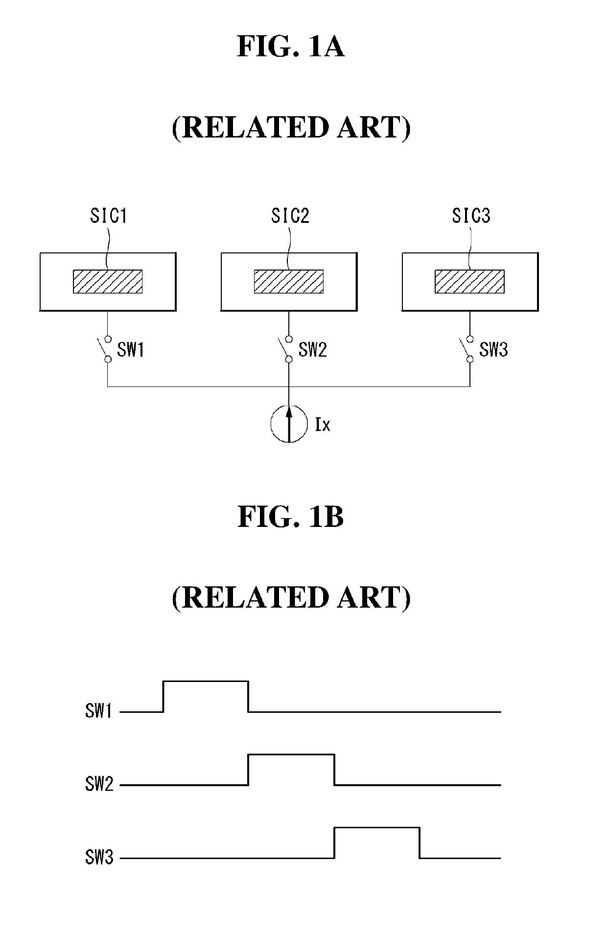
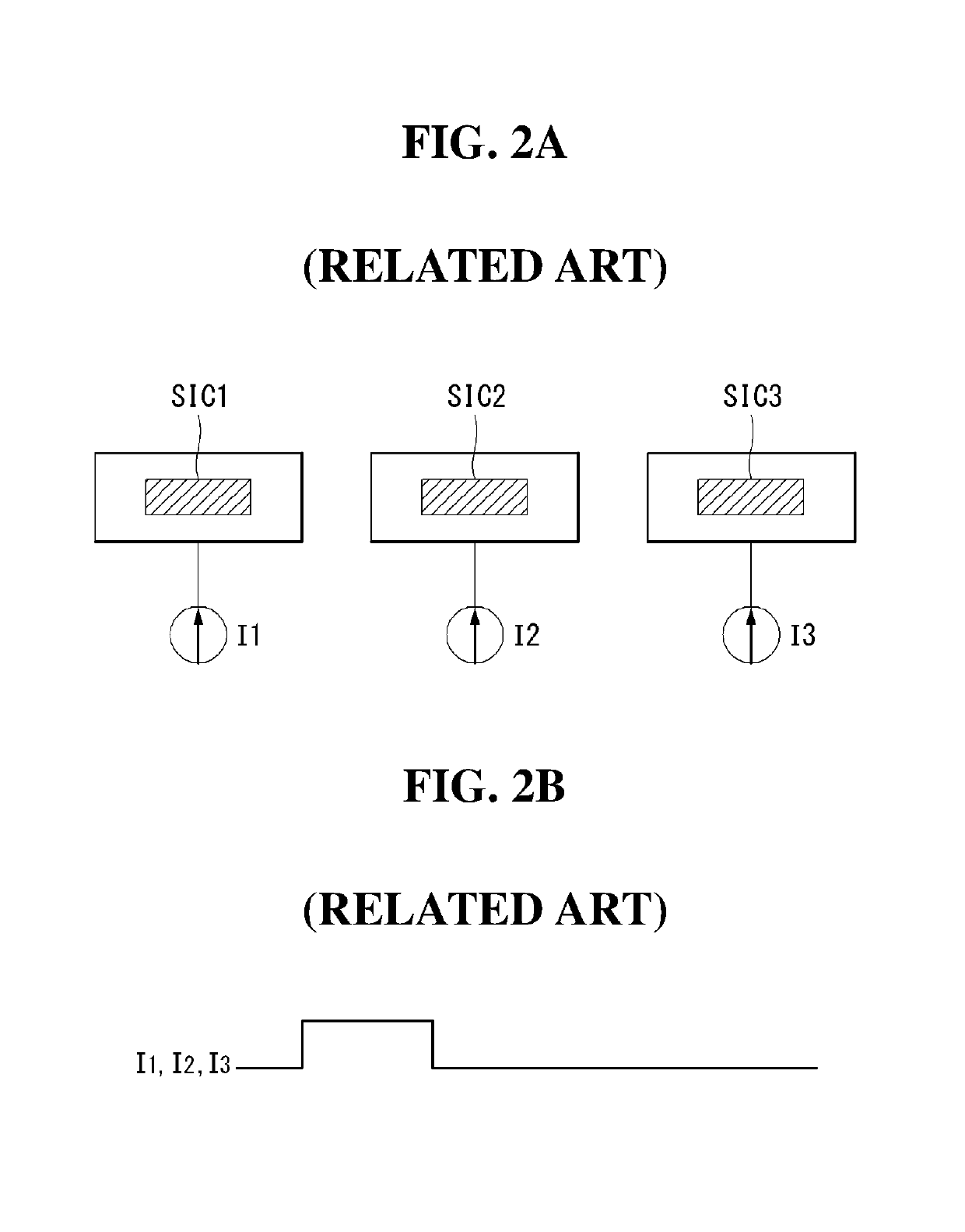
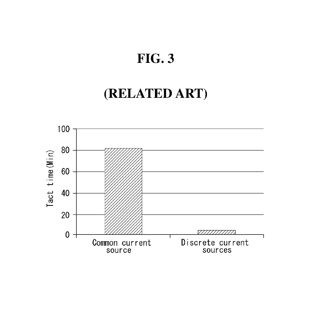
The first calibration method generates no calibration errors due to variations between the current sources because it uses the common current source Ix, but has a problem of increased tack time as shown in FIG. 3 since all of the source drivers ICs SIC1, SIC2, and SIC3 have to be sequentially calibrated with the one common current source Ix.

Method used


Image

  • Calibration device and method and organic light-emitting display including the same
  • Calibration device and method and organic light-emitting display including the same
  • Calibration device and method and organic light-emitting display including the same

Examples


Embodiment Construction

[0046]The advantages and features of the present disclosure and methods of accomplishing the same may be understood more readily by reference to the following detailed descriptions of exemplary aspects and the accompanying drawings. The present disclosure may, however, be embodied in many different forms and should not be construed as being limited to the exemplary aspects set forth herein. Rather, these exemplary aspects are provided so that this disclosure will be thorough and complete and will fully convey the concept of the present disclosure to those skilled in the art, and the present disclosure is defined by the appended claims.

[0047]The shapes, sizes, percentages, angles, numbers, etc. shown in the figures to describe the exemplary aspects of the present disclosure are merely examples and not limited to those shown in the figures. Like reference numerals denote like elements throughout the specification. In describing the present disclosure, detailed descriptions of related ...


PUM


Abstract

An organic light-emitting display comprises: a display panel with a plurality of pixels; a plurality of source driver ICs comprising sensing blocks that are connected to the pixels and sense the electrical characteristics of the pixels; and a calibration block that applies test currents to the sensing blocks in order to sense offset variations between the sensing blocks in a preset calibration mode. The calibration block comprises: a plurality of discrete current sources that generate the test currents; and a switch array that connects the source driver ICs and the discrete current sources, wherein two or more neighboring source driver ICs share one discrete current source, and each source driver IC is selectively connected to two or more discrete current sources.

Description

CROSS REFERENCE TO RELATED APPLICATION[0001]This application claims the priority benefit of Korean Patent Application No. 10-2016-0082729 filed on Jun. 30, 2016, which is hereby incorporated by reference in its entirety for all purposes as if fully set forth herein.BACKGROUND OF THE DISCLOSUREField of the Disclosure[0002]The present disclosure relates to an organic light-emitting display, and more particularly, to a device and calibration method and an organic light-emitting display including the same that is capable of sensing and compensating for variations in electrical characteristics of its pixels.Discussion of the Background[0003]An active-matrix organic light-emitting display comprises self-luminous organic light-emitting diodes (hereinafter, “OLED”), and has the advantages of a fast response time, a high luminous efficiency, a high brightness, and a wide viewing angle.[0004]An OLED, which is a self-luminous device, comprises an anode, a cathode, and organic compound layers H...

Claims


Application Information

Patent Timeline
Patent Type & Authority Patents(United States)
IPC IPC(8): G09G5/00G09G3/3258G09G3/00
CPCG09G3/3258G09G3/006G09G2330/12G09G2320/043G09G2320/0693G09G2320/0285G09G3/3233G09G3/3291G09G3/3275G09G2300/0828G09G2300/0842G09G2310/0297
Inventor KIM, SEUNGTAELIM, MYUNGGIHONG, SEOKHYUN
Owner LG DISPLAY CO LTD
Why Eureka
Try Eureka