Compression ring for tying tree branches

a compression ring and tree branch technology, applied in the field of compression ring, can solve the problems of the inability of high-lifting prior art devices to position the compression ring of the tree branch near the ground beneath the lowest tree branch, a major failing of prior art apparatus, etc., and achieve the effects of reducing friction characteristics, avoiding damage to the tree branch, and being compact and highly maneuverabl

Active Publication Date: 2019-04-09
HERRMANN DOUGLAS
View PDF9 Cites 0 Cited by
  • Summary
  • Abstract
  • Description
  • Claims
  • Application Information

AI Technical Summary

Benefits of technology

[0008]In addition to this novel trailer and frame configuration, the present apparatus includes many other unique features which add to its efficiency and ease of use. For example, the lifting boom utilizes an interconnecting rotation arm between the end of the boom and the compression ring so that the ring may be positioned at a very low starting point close to the ground around the base of the tree trunk, and accurately moved upwardly with the circumference of the ring being held level and centered as the ring is moved upward. With the present invention, this horizontal orientation can be easily maintained as the center of the ring follows the axis of the tree as it is pushed upward to the top. The inability of high lift prior art devices to position the tree branch compression ring close to the ground beneath the lowest tree branches is a major failing of prior art apparatus. The rotation arm provides a double-jointed support of the compression ring that not only more accurately controls its properly aligned upward movement, but also because of its range of movement provides a compacted folded up condition of the boom and compression ring for ease of transportation.
[0009]To further accommodate the flexibility of use and to better achieve proper alignment of the compression ring, a unique frame suspension system has been devised so that support wheels may be both steered and tilted. A steering mechanism provides added maneuverability while a tilt mechanism allows stable placement and centering of the apparatus on uneven ground. Yet another aspect of the invention is a compression ring that includes a specialized lining material which has proven to greatly reduce tree limb damage due to friction between the tree limb bark and the force-applying surface of the ring. The added benefit of reduced friction is a lower power requirement and therefore greater efficiency. Advantageously, the liner is releasably affixed to the outer surfaces of the ring which makes economical the initial fabrication as well as any continuing maintenance or replacement needed. Applicant's discovery of this material for this use is an important aspect of the invention. Other features of the compression ring also contribute to its ease of use and allow “double tying” of larger trees which will be discussed in more detail below.
[0011]In accordance with the foregoing, one object of the invention is to provide a lightweight yet structurally strong standing tree baler apparatus which is compact and highly maneuverable.
[0012]It is another object of the invention to provide a standing tree baler which allows the maximum controlled range of motion of the baling ring while allowing structural ground support directly beneath the ring.
[0013]It is yet another object of the invention to provide a baling ring with reduced friction characteristics to avoid damage to tree branches.
[0014]It is yet another object of the invention to provide a standing tree baler that is economical to use and compactable for ease of transport as a trailered vehicle.

Problems solved by technology

The inability of high lift prior art devices to position the tree branch compression ring close to the ground beneath the lowest tree branches is a major failing of prior art apparatus.

Method used


Image

  • Compression ring for tying tree branches
  • Compression ring for tying tree branches
  • Compression ring for tying tree branches

Examples


Embodiment Construction

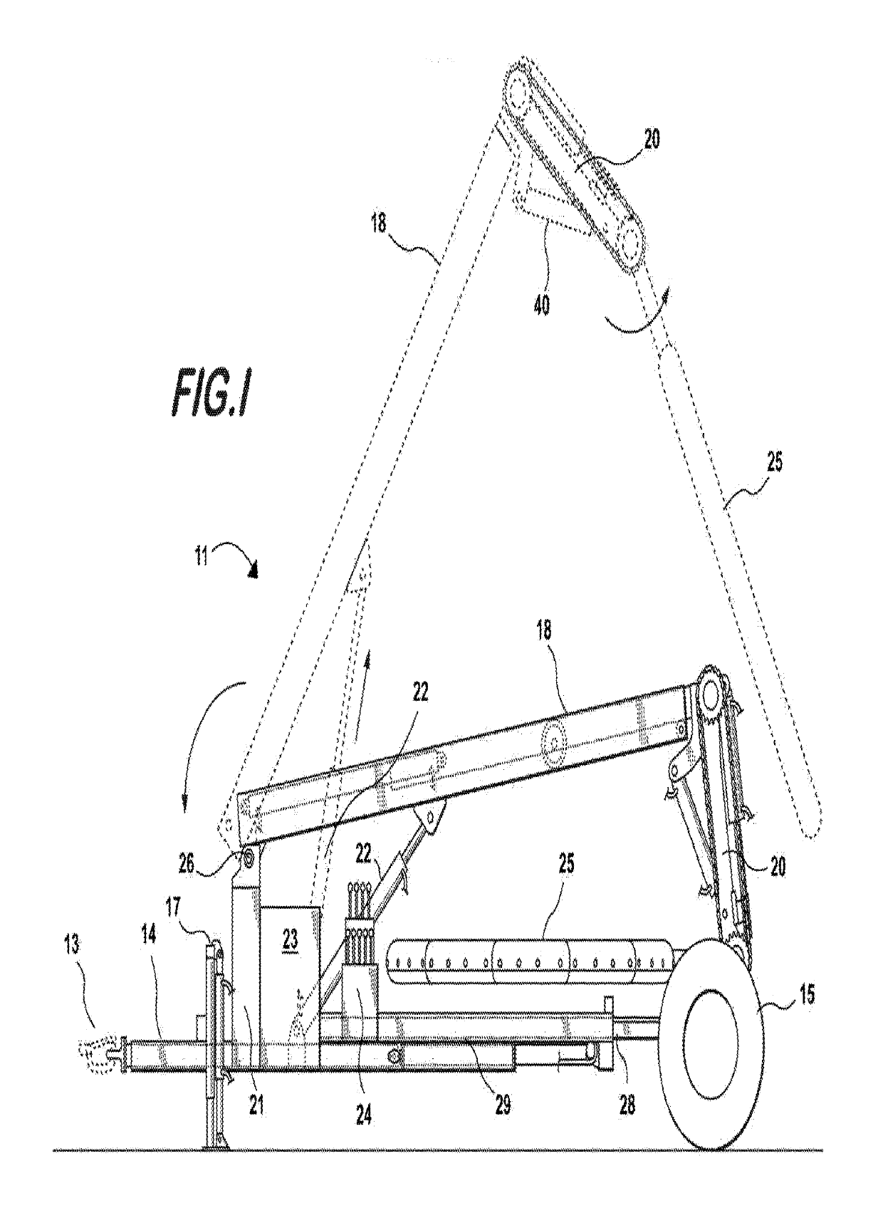
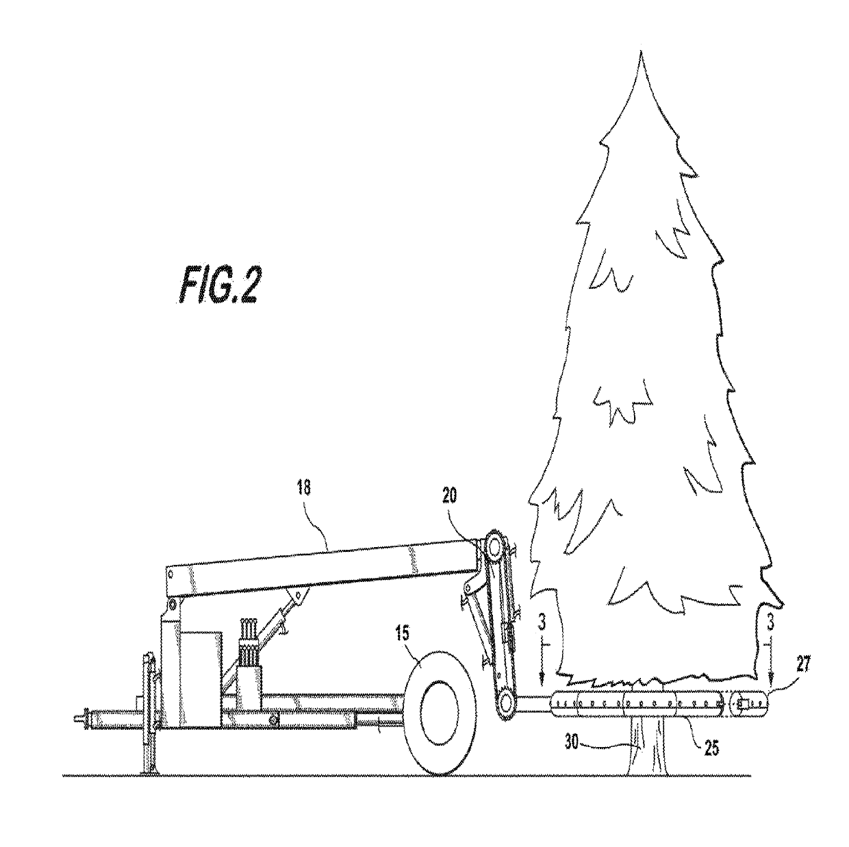
[0048]Referring now to FIG. 1, one embodiment of the tree baler of the invention 11 is constructed in towable trailer configuration with a hitch 13 at the front of a leading end rail 14 and wheels 15 at a trailing end. As depicted, the trailer is unhitched and supported adjacent the leading end by a jack stand 17. In this Figure, the apparatus is shown in its compacted stowed position for transport, and a partially extended position is shown in phantom. Referring to the components of the apparatus in their partially extended position, the apparatus includes a telescoping main boom 18 which supports an articulated rotation arm 20 that in turn pivotably supports the tree branch compression ring 25. The base of the boom is pivotably supported at joint 26 on a main support post 21 and is lifted by hydraulic cylinder 22. A single boom is preferred in that the pivot joint 26 inherently provides an amount of lateral freeplay which permits the ring to self-adjust in response to the force of...


PUM

PropertyMeasurementUnit
angleaaaaaaaaaa
coefficient of frictionaaaaaaaaaa
forceaaaaaaaaaa

Abstract

A standing tree branch compression ring is adapted to be vertically raised about the trunk of the tree by lifting means. As the ring is lifted, the ring forcibly moves the tree branches inward. A plastic ring liner is affixed to the outer surface of the ring to reduce the coefficient of friction of the ring to mitigate tree branch damage. The ring includes a plurality of segments that form a generally toroidal shape and includes a releasable segment to accept the tree trunk from the side. The segment is then connected to the remainder of the ring, around the tree trunk, before the ring is raised.

Description

CROSS-REFERENCE TO RELATED APPLICATIONS[0001]This patent application is a Continuation-in-Part of U.S. patent application Ser. No. 13 / 951,917 entitled “Standing Tree Compression Ring”, filed Nov. 28, 2013, now U.S. Pat. No. 9,809,337 which is a divisional of co-pending patent application Ser. No. 13 / 658,888 entitled “Standing Tree Baler” filed Oct. 24, 2012 which is a divisional of Ser. No. 12 / 730,816 entitled “Standing Tree Baler” filed Mar. 24, 2010 now U.S. Pat. No. 8,347,784 issued Jan. 8, 2013, which are all incorporated herein in their entireties by reference.FIELD OF THE INVENTION[0002]The present invention relates to a device used for compressing the branches of a standing tree in preparation for tying the branches in an upwardly folded condition. More specifically, the invention relates to a compression ring used in conjunction with a standing tree baler.BACKGROUND OF THE INVENTION[0003]Tree baling is well known in the field of handling commercial nursery stock. In many cas...

Claims


Application Information

Patent Timeline
Patent Type & Authority Patents(United States)
IPC IPC(8): B65B11/02A01G23/04B65B13/20B65B25/02
CPCB65B11/025B65B25/02B65B13/20A01G23/04
Inventor HERRMANN, DOUGLAS S.MARO, SCOTT J.
Owner HERRMANN DOUGLAS
Why Eureka
Try Eureka