Twist-on wire connector

a wire connector and twisting technology, applied in the direction of connecting with permanent deformation, basic electric elements, electrical apparatus, etc., can solve the problems of difficult spring assembly methods, time-consuming, and expensive, and achieve the effect of comfortable grip

Active Publication Date: 2019-04-23
THOMAS & BETTS INT INC
View PDF25 Cites 0 Cited by
  • Summary
  • Abstract
  • Description
  • Claims
  • Application Information

AI Technical Summary

Benefits of technology

[0006]According to an embodiment of the present invention, a twist-on wire connector includes a connector cap and a tapered coil spring configured to be secured within the connector cap. The connector cap includes a peripheral wall extending between open and closed ends of the connector cap and defining a connector cap recess, top portion having the closed end, bottom portion having the open end, and asymmetrically opposed wings. The asymmetrically opposed wings are positioned to offset from a centerline of the connector cap to provide a comfortable grip while turning the twist-on wire connector during electrical wire installation.

Problems solved by technology

While the wings provide a grip for installer's fingers, this configuration of the wings does not provide a fully comfortable grip when turning the connector cap.
However, these spring assembly methods are difficult to perform, time consuming, and expensive.

Method used


Image

  • Twist-on wire connector
  • Twist-on wire connector
  • Twist-on wire connector

Examples


Embodiment Construction

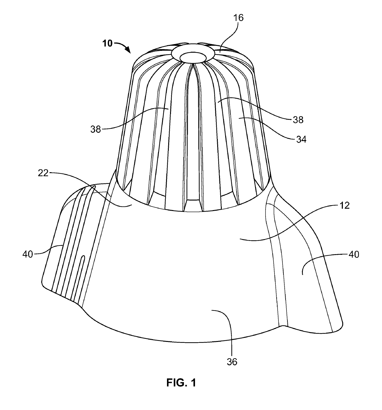
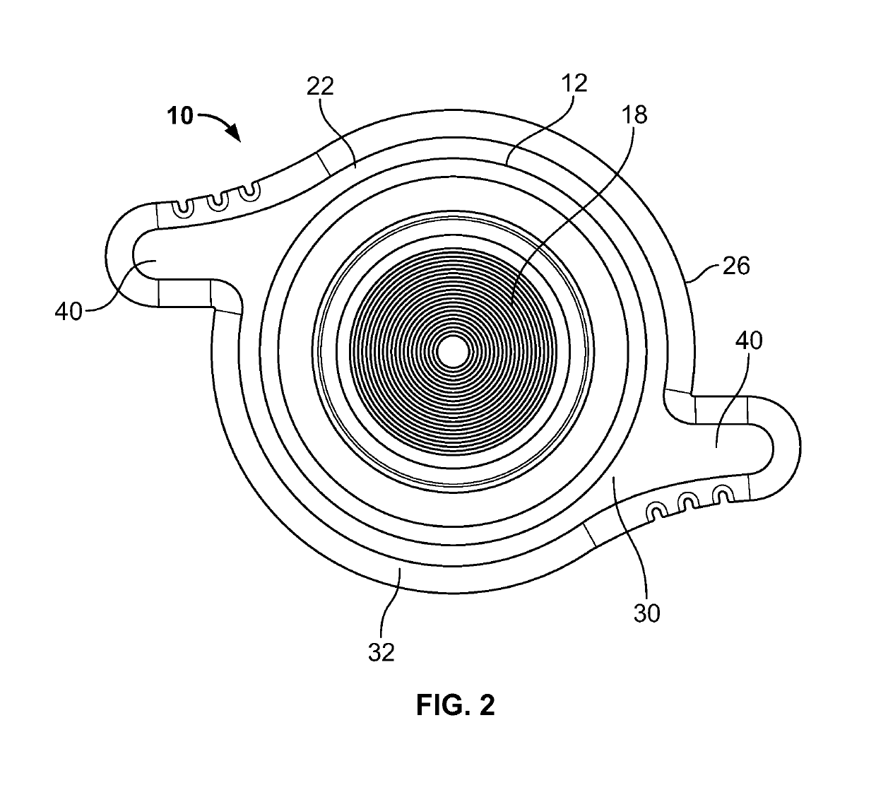
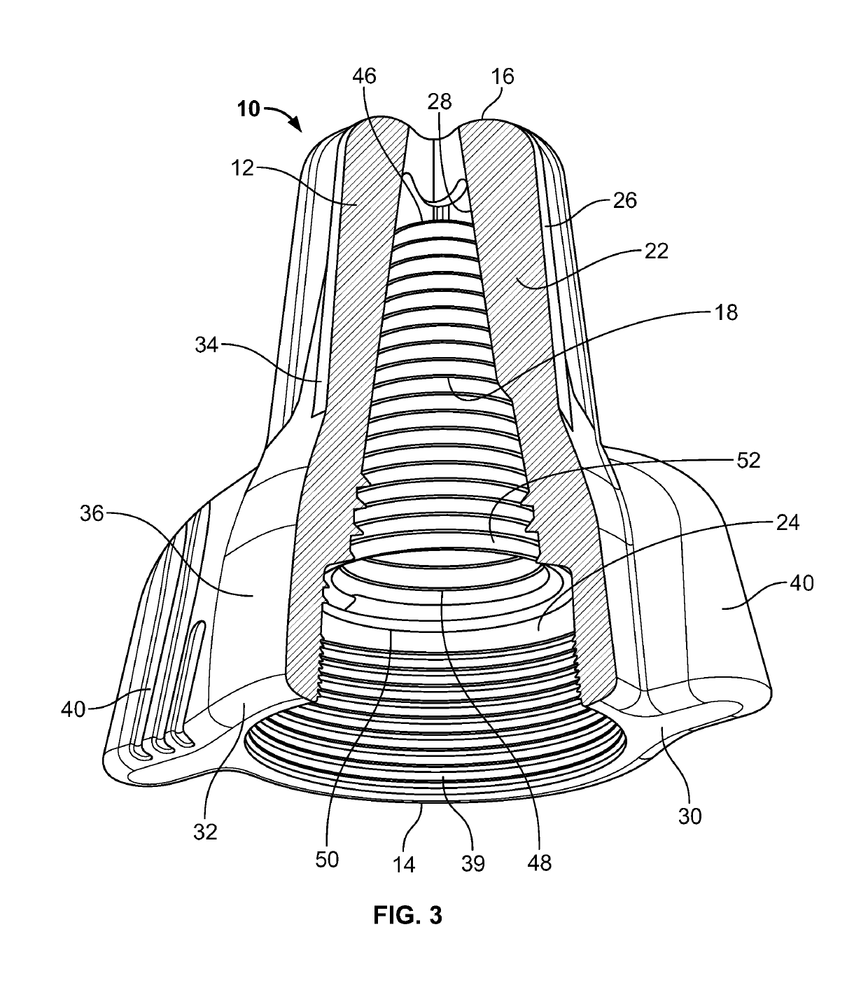
[0018]According to an embodiment of the present invention, referring to FIGS. 1-3, there is shown a twist-on wire connector 10 adapted and used for splicing the ends of electrical wires. The twist-on wire connector 10 includes a connector cap 12 having an open end 14 and a rounded closed end 16, and a tapered coil spring 18, which is designed and configured to be placed within the connector cap 12, as illustrated in FIGS. 2 and 3. The tapered coil spring 18 is secured within the connector cap 12 using a punch, as will be described in greater detail below.

[0019]Directional terms, such as top and bottom are referenced to an orientation in which the twist-on wire connector 10 is placed on a flat surface with the closed end 16 facing upwards. However, the present invention is not thereby limited to use in any particular orientation.

[0020]Referring to FIGS. 3 and 4, the connector cap 12 is generally hollow having a cylindrical or conical shape. The connector cap 12 includes a peripheral ...


PUM


Abstract

A twist-on wire connector includes a connector cap and a tapered coil spring configured to be secured within the connector cap. The connector cap includes a peripheral wall extending between open and closed ends of the connector cap and defining a connector cap recess, top portion having the closed end, bottom portion having the open end, and asymmetrically opposed wings. The asymmetrically opposed wings are positioned to offset from a centerline of the connector cap to provide a comfortable grip while turning the twist-on wire connector during electrical wire installation.

Description

CROSS REFERENCE TO RELATED APPLICATION[0001]This application claims priority to U.S. Provisional Patent Application No. 62 / 463,140, filed on Feb. 24, 2017, the contents of which are incorporated herein by reference in its entirety.FIELD OF THE INVENTION[0002]The present invention relates to wire connectors, and more particularly, to twist-on wire connectors configured to provide more comfortable grip thereon and to facilitate easy installation of a spring within the twist-on wire connectors.BACKGROUND OF THE INVENTION[0003]Twist-on wire connectors are used to fasten a plurality of electrical wires. These connectors are available in various sizes and shapes, and each connector typically has a conical shape composed of insulative material. Generally, each of the twist-on wires currently available in the market includes a connector cap and a tapered coil spring. Some of the twist-on wire connectors further include a pair of opposed wings to provide a comfortable grip while installing / u...

Claims


Application Information

Patent Timeline
Patent Type & Authority Patents(United States)
IPC IPC(8): H01R4/12H01R4/48H01R43/20H01R4/22
CPCH01R4/4863H01R4/12H01R4/22H01R4/48H01R43/20
Inventor LEGAULT, LUDOVIC
Owner THOMAS & BETTS INT INC
Why Eureka
Try Eureka