Foamed celluloid delay fuze

Active Publication Date: 2019-06-11
UNITED STATES OF AMERICA THE AS REPRESENTED BY THE SEC OF THE ARMY
View PDF18 Cites 1 Cited by
  • Summary
  • Abstract
  • Description
  • Claims
  • Application Information

AI Technical Summary

Benefits of technology

[0009]The present invention satisfies this need, and describes a safety fuze for hand-emplaced grenades, which uses a non-energetic delay mixture. More specifically, the delay mixture uses foam celluloid in lieu of the conventio

Problems solved by technology

However, these conventional designs could present various inherent problems, particularly when used in the field, under adverse and stressful conditions.
These concerns arise from the dwell time requirement between the activation of the grenade to the detonation.
The issue of

Method used


Image

  • Foamed celluloid delay fuze
  • Foamed celluloid delay fuze
  • Foamed celluloid delay fuze

Examples


Embodiment Construction

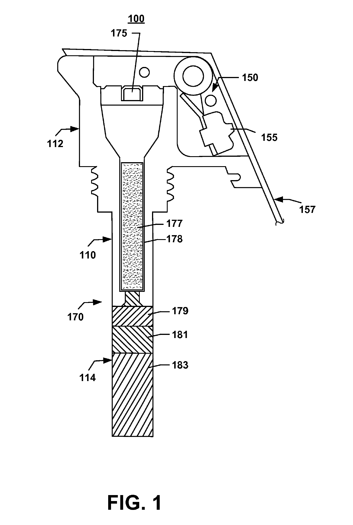
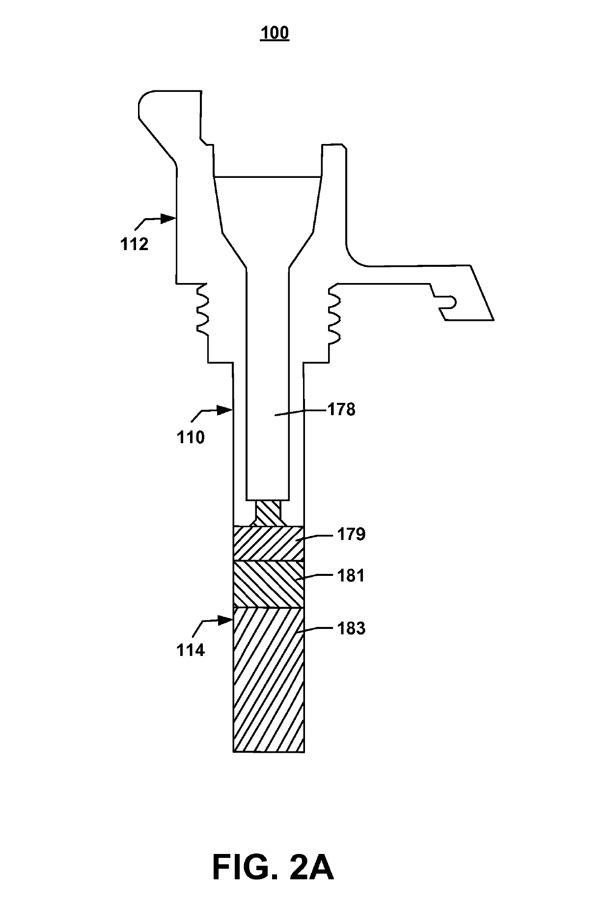
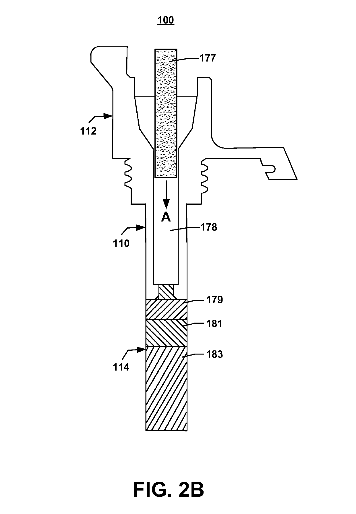
[0029]A safety fuze 100 of the present invention and its method of assembly and operation will now be described with reference to FIGS. 1 and 3. The safety fuze 100 generally includes a fuze body 110, a trigger mechanism 150, and an energetic train 170.

[0030]The fuze body 110 is formed of an upper fuze body 112 and a lower fuze body 114. The upper fuze body 112 is secured to the trigger mechanism 150. In this exemplary embodiment, the trigger mechanism 150 includes a firing pin 155 and a handle 157.

[0031]The upper fuze body 112 includes a threaded section 115 that enables a grenade 300 (FIG. 3) or another military or commercial explosive device to be attached to the safety fuze 100. The section 115 is not limited to the illustrated threaded configuration. Rather, it could be shaped to best suit the application for which it is designed.

[0032]Depending on the specific application, the design of the safety fuze 100 may require the energetic train 170 to be formed of a plurality of sequ...


PUM


Abstract

A safety fuze for use in military and commercial applications, includes a fuze body that is attached to a trigger mechanism, an energetic train contained within the fuze body, and a non-energetic fuze delay mixture that is formed in a rod form so that it can dropped inside the fuze body, without modification to the other components of the safety fuze. Preferably, the non-energetic fuze delay mixture is made of foamed celluloid.

Description

GOVERNMENTAL INTEREST[0001]The invention described herein may be manufactured and used by, or for the Government of the United States for governmental purposes without the payment of any royalties thereon.FIELD OF THE INVENTION[0002]The present invention relates in general to the field of munitions. More specifically, this invention relates to hand emplaced grenades that are provided with a safety fuze using a non-energetic mixture as a fuze delay composition. The safety fuze may be used in military and commercial applications.BACKGROUND OF THE INVENTION[0003]Safety is a very important design aspect of a hand grenade (or an explosive) fuze in military and commercial applications. Conventional fuze designs account for a time delay period from initiation, for the detonation to occur, in order to ensure that the grenade is cast outside the explosion hazard area.[0004]To this end, numerous conventional hand grenade fuzes have been proposed, some of which are described in the following p...

Claims


Application Information

Patent Timeline
IPC IPC(8): F42C9/10F42B27/00F42B27/08F42C9/14
CPCF42C9/10F42B27/00F42B27/08F42C9/14F42C9/142F42C14/02
Inventor ELALEM, MOHAMEDABBATE, PHILIPGONSALVES, VINCENTEVANGELISTI, MATTHEW P.GRASSIA, JOHN W.KOTEFSKI, STEVEKOTEFSKI, NIKOLAYOUNG, MING-WANSHEN, FEIPENG, CHONGZHU, LINJIEPANCHAL, VIRAL
Owner UNITED STATES OF AMERICA THE AS REPRESENTED BY THE SEC OF THE ARMY
Why Eureka
Try Eureka