Connection structure of intake manifold and egr system

A technology of intake manifold and intake branch pipe, which is applied in the field of connection structure between intake manifold and EGR system, can solve problems such as inconsistency of EGR gas flow, and achieve the effects of consistent combustion rate, improved efficiency, and consistent flow

Active Publication Date: 2022-02-25
ANHUI JIANGHUAI AUTOMOBILE GRP CORP LTD
View PDF7 Cites 0 Cited by
  • Summary
  • Abstract
  • Description
  • Claims
  • Application Information

AI Technical Summary

Problems solved by technology

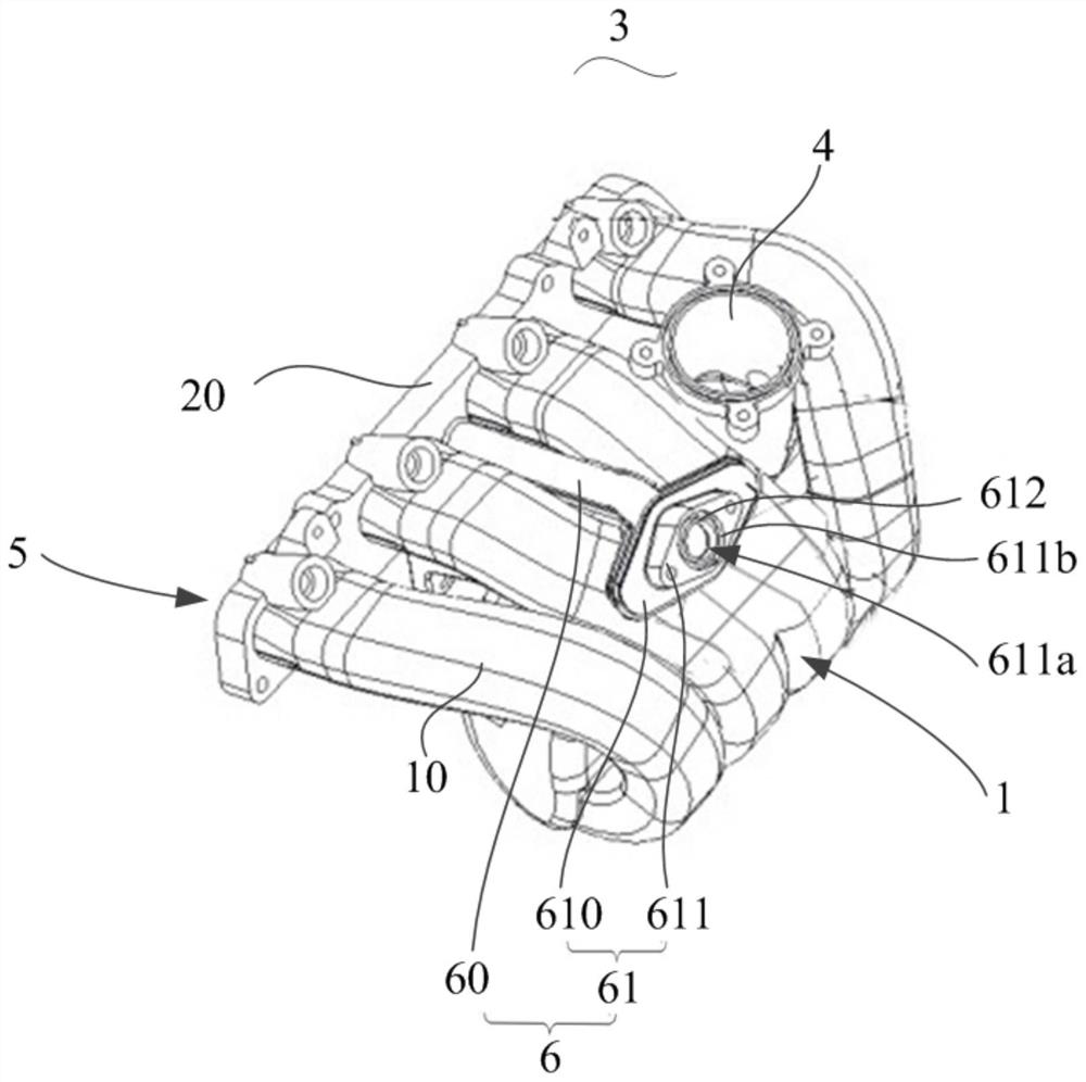
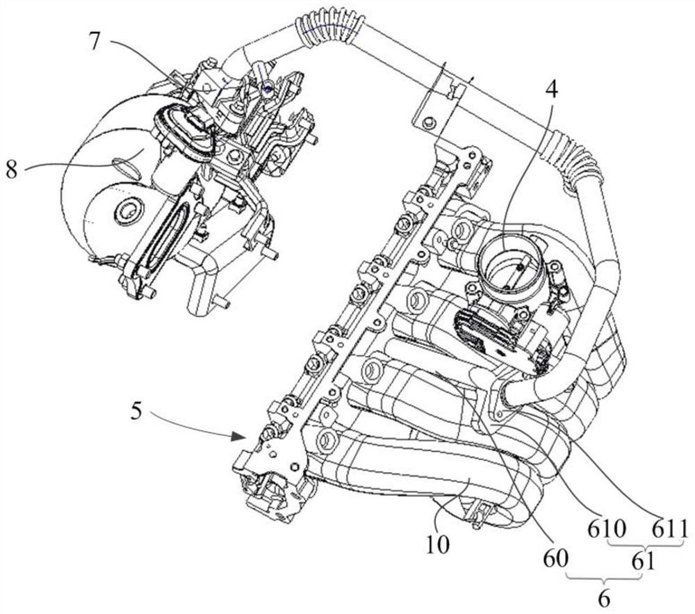
[0006] The main purpose of the present invention is to propose an intake manifold, which aims to solve the problem of inconsistency in the flow of EGR gas entering the cylinder of the engine in the prior art

Method used


Image

  • Connection structure of intake manifold and egr system
  • Connection structure of intake manifold and egr system
  • Connection structure of intake manifold and egr system

Examples


Embodiment Construction

[0027] The technical solutions in this embodiment will be clearly and completely described below in conjunction with the accompanying drawings in this embodiment. Obviously, the described embodiments are only part of the embodiments of the present invention, not all of them. Based on the embodiments of the present invention, all other embodiments obtained by persons of ordinary skill in the art without creative efforts fall within the protection scope of the present invention.

[0028] It should be noted that all directional indications (such as up, down, left, right, front, back...) in this embodiment are only used to explain the relative relationship between the various components in a certain posture (as shown in the figure). When the positional relationship, movement conditions, etc., if the specific posture changes, the directional indication will also change accordingly.

[0029] In addition, in the present invention, descriptions such as "first", "second" and so on are ...


PUM


Abstract

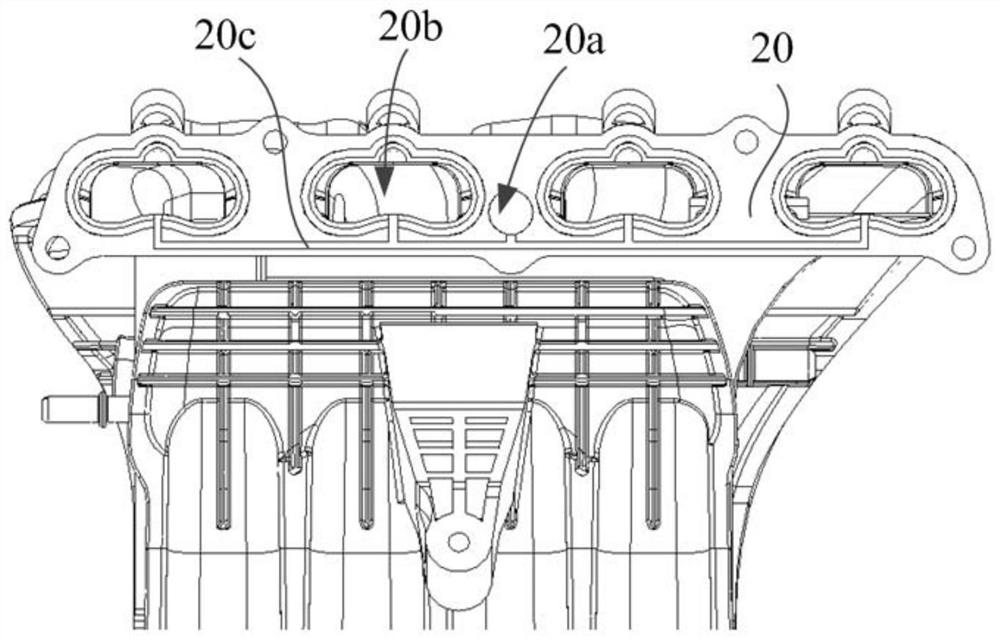
The invention discloses a connection structure between an intake manifold and an EGR system. One end of the intake manifold is used to connect with the throttle valve of the engine, and the other end of the intake manifold is used to connect with the intake valve of the engine. The pipe includes a manifold body and a connection assembly. The manifold body includes a plurality of intake branch pipes for communicating with the throttle valve respectively; The number of intake branch pipes is corresponding and connected to the connection hole. The connection cover protrudes away from the intake branch pipe to form a channel. The channels are respectively connected to the through hole and the connection hole. It is used to connect with the engine cylinder head and cover the intake valve. By opening a through hole on the connection cover, the EGR gas can flow directly from the through hole into the engine cylinder, so that the EGR gas flow into the engine cylinder is consistent and improves the efficiency of the engine.

Description

technical field [0001] The invention relates to the technical field of engines, in particular to a connection structure between an intake manifold and an EGR system. Background technique [0002] The engine is equipped with an intake valve and a throttle valve. The throttle valve is used to control the amount of gas entering the engine, and the intake valve is used to control the amount of gas entering the engine cylinder. [0003] At present, in order to improve the economy of the engine and reduce fuel consumption, EGR (Exhaust Gas Recirculation, exhaust gas recirculation) technology is usually used. EGR refers to reintroducing part of the exhaust gas discharged from the exhaust hole (or three-way catalytic converter) to the intake manifold. In the tube, part of the exhaust gas and fresh air are introduced into the combustion chamber for combustion. [0004] EGR in the prior art usually introduces the EGR gas drawn from the gas outlet of the three-way catalytic converter ...

Claims


Application Information

Patent Timeline
Patent Type & Authority Patents(China)
IPC IPC(8): F02M35/104F02M35/10F02M26/01F02M26/12
CPCF02M35/104F02M35/10222F02M26/01F02M26/12
Inventor 陈友祥韩丹罗亚伟
Owner ANHUI JIANGHUAI AUTOMOBILE GRP CORP LTD
Why Eureka
Try Eureka