Medical device

a medical device and calcification lesion technology, applied in the field of medical devices, can solve the problems of difficult to collect debris insufficient quantity, difficult to treat stenosis with these methods, and difficult to collect calcified lesions having particularly high hardness

Pending Publication Date: 2022-11-17
TERUMO KK
View PDF0 Cites 0 Cited by
  • Summary
  • Abstract
  • Description
  • Claims
  • Application Information

AI Technical Summary

Benefits of technology

[0018]In the medical device configured as described above, the driving of the fluid driving source is started first, and the driving of the drive shaft driving source is started with a delay, and thus the cutting by the cutter is started after a sufficient negative pressure is generated at a distal portion of the lumen. A delay time from a start of aspiration in the lumen to a start of rotation of the cutting portion can be freely set and stored in the controller, and the start of the driving of the drive shaft driving source can be reliably delayed regardless of a state of the first switch.

Problems solved by technology

However, it is difficult for these methods to treat a stenosed site that is hardened by calcification or a stenosed site that is formed at a bifurcated portion in the blood vessel.
Examples of a risk of a procedure by such an atherectomy device include peripheral embolization due to debris caused by a plaque or the like cut by the atherectomy device.
There exists a medical device using a mechanical cutting method and having a function of taking debris into a lumen of the medical device, but it is difficult to collect a calcified lesion having particularly high hardness.
Therefore, there is a high risk that the negative pressure for drawing debris into the lumen is not sufficient immediately after the start of the rotation of the cutting portion, and the debris cannot be sufficiently collected immediately after the start of the rotation.
However, since the switch of the motor is operated by the mechanical mechanism, a delay time from the start of the aspiration in the lumen to a start of rotation of the motor cannot be adjusted.
Therefore, a sufficient delay time may not be obtained.
In addition, the functionality of the medical device depends on rigidity of a tube, and a tube having the lumen may be crushed.

Method used


Image

  • Medical device
  • Medical device
  • Medical device

Examples


Embodiment Construction

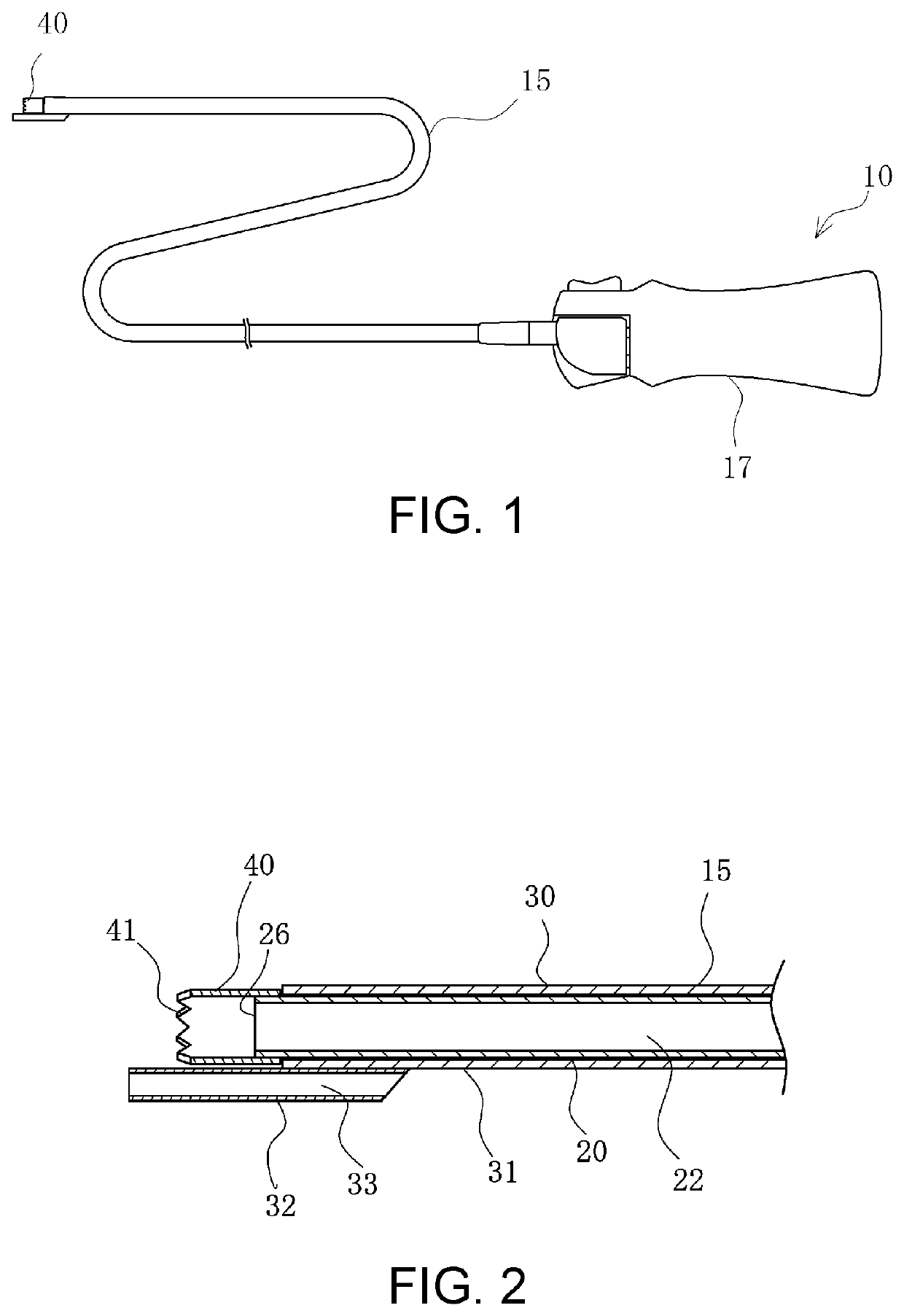
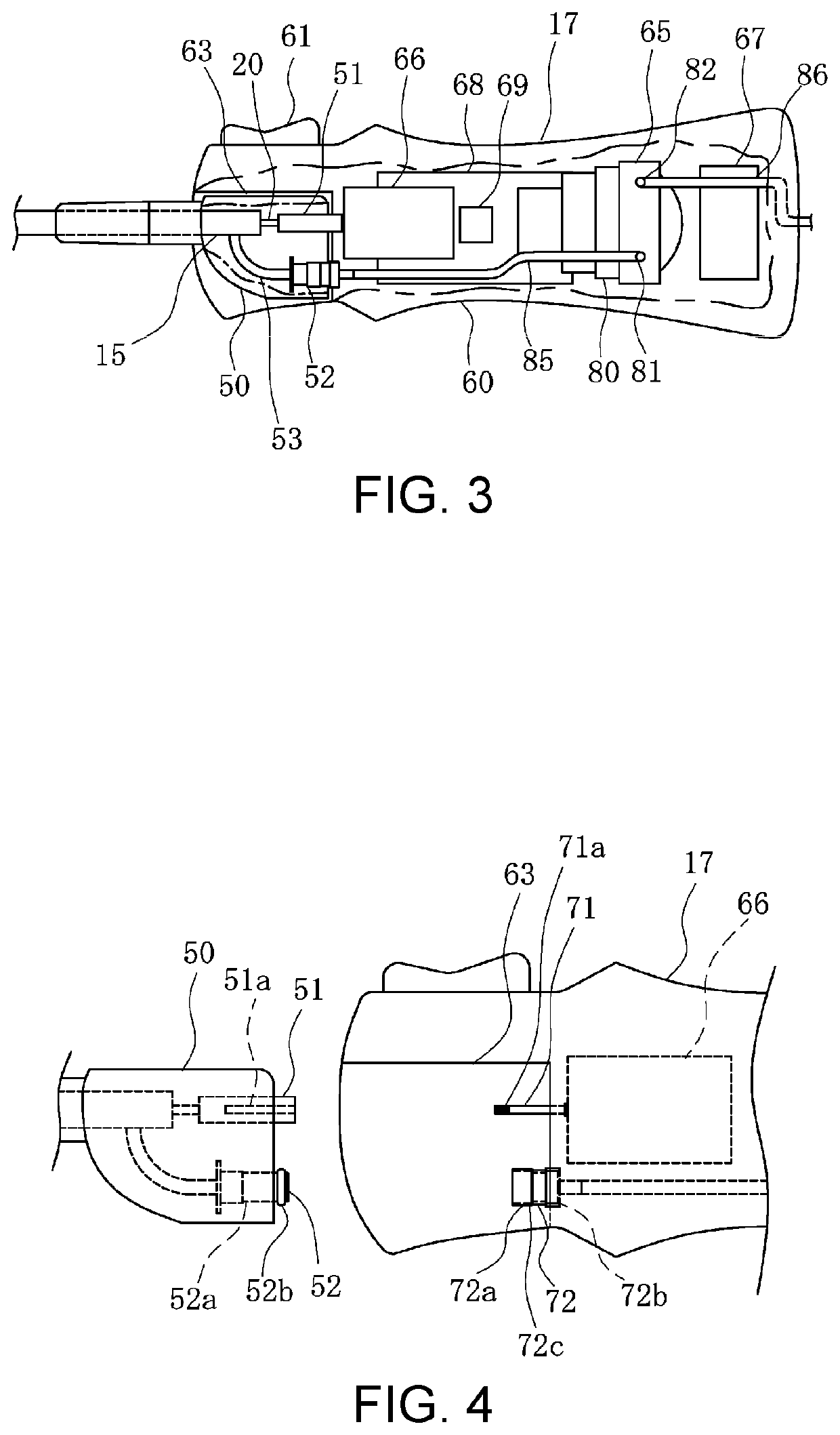
[0028]Hereinafter, embodiments according to this disclosure will be described with reference to the drawings. It is noted that dimensional ratios in the drawings are exaggerated for convenience of description and may differ from actual ratios. In the present specification, a side of a medical device 10 to be inserted into a body cavity is referred to as a “distal end” or a “distal side”, and a side to be operated by an operator is referred to as a “proximal end” or a “proximal side”.

[0029]The medical device 10 according to an embodiment is inserted into a blood vessel in an acute lower limb ischemia or a deep vein thrombosis, and is used for a procedure for destroying and removing a thrombus, a plaque, an atheroma, a calcified lesion, and the like. It is noted that an object to be removed is not necessarily limited to the thrombus, the plaque, the atheroma, and the calcified lesion, and any object that may be present in a body lumen or a body cavity can be removed by the medical dev...


PUM


Abstract

A medical device for removing an object in a body cavity, includes a rotatable drive shaft having a lumen, a cutter disposed at a distal portion of the drive shaft and by which the object is cut, a drive shaft driving source configured to rotate the drive shaft, a fluid driving source configured to move a fluid from a distal side to a proximal side of the lumen, a switch, and a controller configured to, in response to the switch being turned on, control the fluid driving source to begin moving the fluid, and control the drive shaft driving source to begin rotating the drive shaft a first predetermined period after the switch is turned on.

Description

CROSS-REFERENCE TO RELATED APPLICATION(S)[0001]This application is a continuation of International Patent Application No. PCT / JP2020 / 014690 filed Mar. 30, 2020, the entire contents of which are incorporated herein by reference.BACKGROUND OF THE INVENTIONField of the Invention[0002]This disclosure relates to a medical device for removing an object in a body cavity and a method performed by a medical device.Background Art[0003]Examples of a treatment method for a stenosed site caused by a plaque, a thrombus, and the like in a blood vessel include a method for dilating the blood vessel by using a balloon, and a method for causing a mesh-shaped or coil-shaped stent to indwell the blood vessel as a support for the blood vessel. However, it is difficult for these methods to treat a stenosed site that is hardened by calcification or a stenosed site that is formed at a bifurcated portion in the blood vessel. Thus, methods for cutting and removing a stenotic material such as a plaque or a th...

Claims


Application Information

Patent Timeline
Patent Type & Authority Applications(United States)
IPC IPC(8): A61B17/3207
CPCA61B17/320758A61B2017/00539A61B2217/005A61B2017/22041A61B2217/007A61B2017/00022
Inventor KOBAYASHI, JUNICHITADA, YUICHI
Owner TERUMO KK
Why Eureka
Try Eureka