Floating debris remover

a technology of floating debris and remover, which is applied in water cleaning, special-purpose vessels, vessel parts, etc., can solve the problems of unsightly and difficult to navigate lakes, unwanted spread of harmful invasive weeds, unsightly and polluting debris,

Active Publication Date: 2019-06-18
NICKELSON DAVID
View PDF14 Cites 19 Cited by
  • Summary
  • Abstract
  • Description
  • Claims
  • Application Information

AI Technical Summary

Benefits of technology

This patent describes a device that removes debris from waterways by using a mobile platform equipped with a suction system to pull debris into its interior. An operator can use the device to collect and dispose of debris while maintaining safety standards. It has two modes: a debris removal mode where it uses electric motors to manage its speed and direction, and a transport mode where it utilizes a stronger engine to easily move between different locations. Additionally, the device includes an anchor pole to secure it when positioned near a waste containment area. Overall, this technology allows for efficient and safe cleanup of marine environments without requiring significant human labor.

Problems solved by technology

The technical problem addressed in this patent text is the need for an efficient way to remove unsightly and polluting debris from lakes and other bodies of water, particularly in marinas with multiple docks or isolated docks. The debris can be time-consuming and difficult to remove, and there is a need for an operator controlled debris remover that can collect and remove the debris from the lake and transfer it to a site for disposal.

Method used


Image

  • Floating debris remover
  • Floating debris remover
  • Floating debris remover

Examples


Embodiment Construction

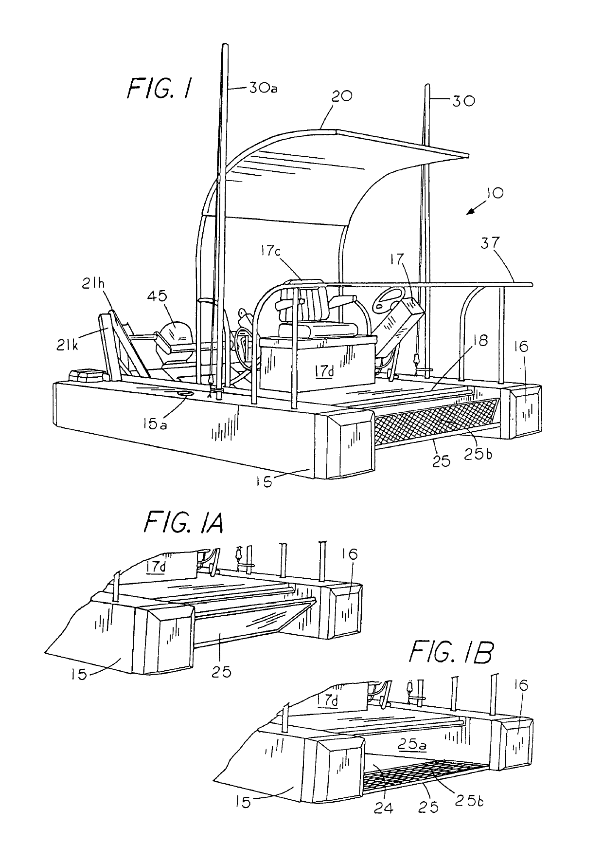
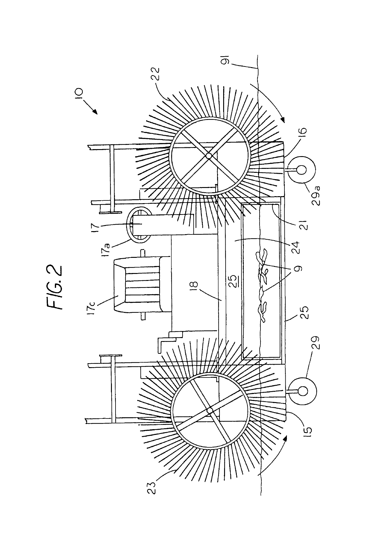
[0030]FIG. 1 is a perspective view of an operator driven, floating debris remover 10 with a deck 18 supported by a pair of pontoons 15, 16 with the floating debris remover having a control station 17, a handrail 37, a storage container 17d, an operator seat 17c, a canopy 20 and an outboard motor 45. A manipulateable flow through debris scoop 21, which is located between outer pontoons 15 and 16 and in the rear of the debris remover 10, is shown in an isolated view in FIG. 3. The debris scoop is operator manipulateable through a set of pivot arms 21k and 21h and pivot arms 21f and 21g (FIG. 3), which are typically operator controlled through a first power cylinder 21r and a second power cylinder 21s, which may be hydraulic cylinders or the like. That is, the debris remover 10 lift arm 21f and lift arm 21h elevates the tiltable screen bucket or tiltable scoop 21 from a debris harvesting position between the set of pontoons (FIG. 2) to a debris empting condition proximate a refuse cont...


PUM


Abstract

A floating debris remover having an operator station for directing debris into a debris inlet and a power manipulateable debris scoop for on-the-go separation of the debris from the water through elevation of the debris scoop with the debris remover having an operator station to allow an onboard operator to retrieve and deposit debris at a waste disposal site solely through operator manipulation of the debris scoop.

Description


Claims


Application Information

Patent Timeline
Owner NICKELSON DAVID
Why Eureka
Try Eureka