
Reconfigurable exoskeleton

a technology of exoskeleton and limb, which is applied in the field of powerless lower extremity exoskeleton, can solve the problems of reducing the number of people with impaired lower extremity function

Active Publication Date: 2019-06-25
EKSO BIONICS
View PDF51 Cites 1 Cited by
  • Summary
  • Abstract
  • Description
  • Claims
  • Application Information

AI Technical Summary

Benefits of technology

The patent describes several devices that enable users to adjust and control the movement of an exoskeleton joint in real-time, making it easier for a wider range of people to use. These devices include a modular joint system that allows for individual joints to be swapped, an actuated joint that can be adjusted using software, and a pair of mechanically unlocking joints that allow for pivoting or non-pivoting in an axis that is not actuated. Overall, these features expand the intended user population for a particular exoskeleton device.

Problems solved by technology

Nevertheless, these devices have generally neglected a larger population of persons with impaired lower extremity function, particularly persons who have survived a stroke.
Stroke survivors often exhibit hemiparetic injuries, where one limb is much more severely impaired than the other.
While some devices have been designed that provide one powered degree of freedom, such as a powered knee brace, these devices can only help those with more mild injuries, and cannot accommodate as severely impaired a person as a full exoskeleton.
Furthermore, these devices result in a significant weight borne by the person on their less impaired leg, which must support the weight of the device when the more impaired leg is in swing; this effect is compounded for heavier devices with two or more degrees of freedom.
Finally, the out-of-plane axes in powered lower extremity exoskeletons known in the art are locked, something essential for persons who are completely paralyzed, but that is restrictive for persons who are hemiplegic.
This determination is one of the primary factors limiting the intended user population of an exoskeleton device; for example if a joint is fixed and a user requires the joint to freely rotate the user cannot use the exoskeleton device.

Method used


Image

  • Reconfigurable exoskeleton
  • Reconfigurable exoskeleton
  • Reconfigurable exoskeleton

Examples


Embodiment Construction

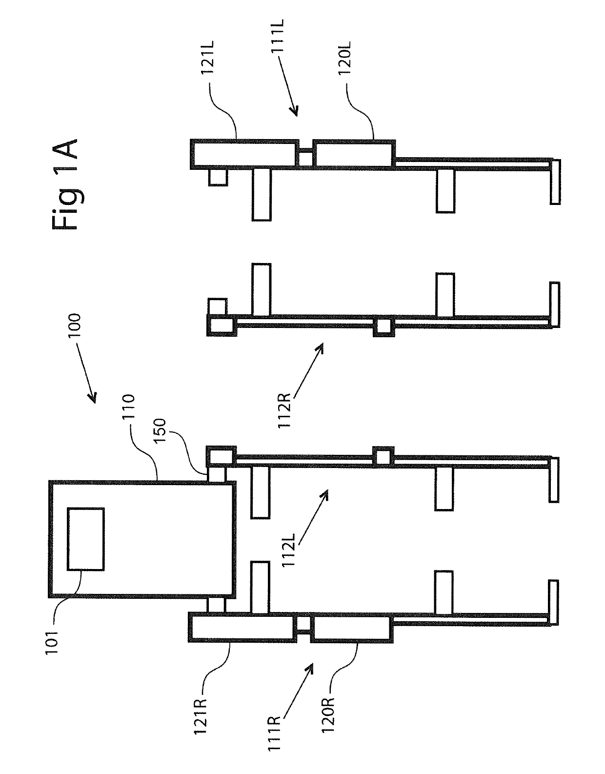
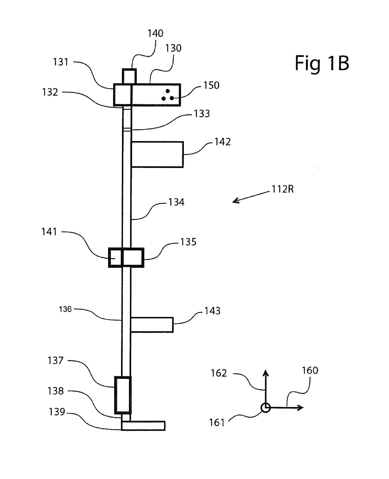
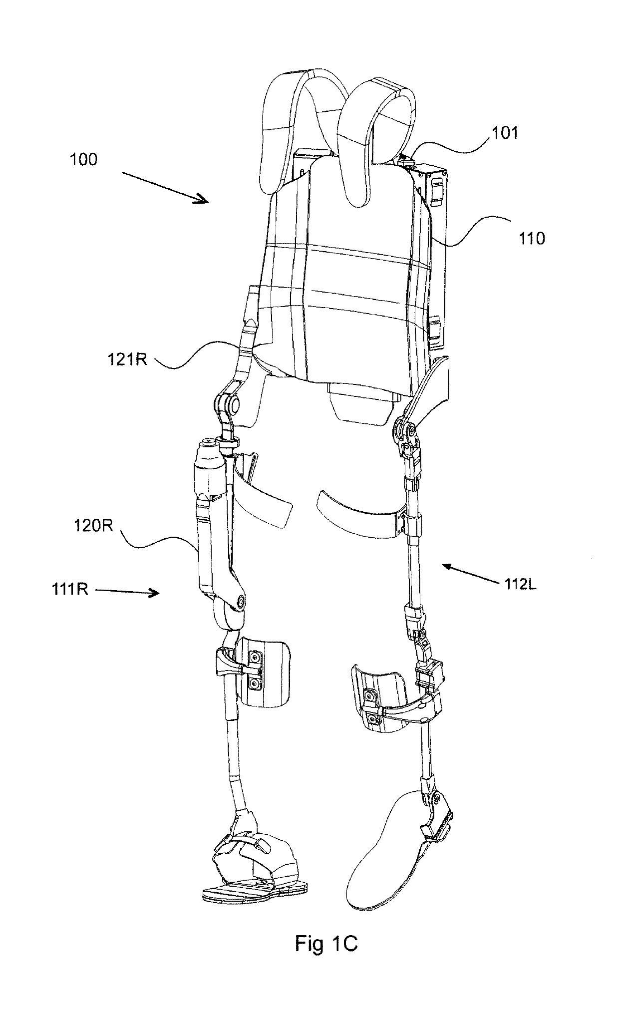
[0024]Extensive testing performed with stroke patients done under a human subject protocol suggested that stroke patients with a chronic injury can benefit from an exoskeleton where the legs may be swapped so that only one side of the exoskeleton is actuated. This knowledge led to a first category of modular systems incorporating torque modifiers in accordance with the invention as will now be described. In general, the first embodiment allows a single exoskeleton to enable paraplegics to walk and aid in the gait training of stroke patients. These two populations are best served by different configurations of an exoskeleton device. A complete paraplegic may lack any muscular control below a certain level; in this case each degree of freedom of the person must be controlled—either with a motor, a passive element such as a spring or a damper, or by simply locking the degree of freedom altogether. Conversely, a stroke patient may have a less affected side with almost normal muscular co...


PUM


Abstract

An exoskeleton can be reconfigured, adjusted and / or controlled on the fly utilizing devices which fall into three categories, particularly including a swappable unactuated leg, lockable transverse and coronal hip rotations, and software controlled free joints. More specifically, the first device allows for the creation of a modular joint system in which individual exoskeleton joints or limbs can be changed or swapped to optimize an exoskeleton for a particular user. The second device is concerned with mechanically controlling, such as locking and unlocking, joints thereby allowing, for example, an exoskeleton leg to pivot or not pivot in an axis that is not actuated. The third device allows an actuated exoskeleton joint to be adjusted on the fly using software to simulate a freely rotating joint. The various devices can be used either alone or in combination to enable any given exoskeleton to be appropriately reconfigured, such as when a patient advances during therapy.

Description

CROSS-REFERENCE TO RELATED APPLICATIONS[0001]The present application represents a National Stage application of PCT / US2013 / 074353 entitled “Reconfigurable Exoskeleton” filed Dec. 11, 2013, which claims the benefit of U.S. Provisional Patent Application Ser. No. 61 / 735,816 filed Dec. 11, 2012 and entitled “Reconfigurable Exoskeleton”.BACKGROUND OF THE INVENTION[0002]In the art of powered lower extremity exoskeletons, especially where at least two degrees of freedom of the exoskeleton leg are actuated, the main application has been helping persons with complete lower extremity paralysis walk. Several devices have been or are being commercialized for this application. Nevertheless, these devices have generally neglected a larger population of persons with impaired lower extremity function, particularly persons who have survived a stroke. Stroke survivors often exhibit hemiparetic injuries, where one limb is much more severely impaired than the other. While some devices have been design...

Claims


Application Information

Patent Timeline
Patent Type & Authority Patents(United States)
IPC IPC(8): A61H1/02B25J9/00A61H3/00
CPCA61H1/024A61H1/0244A61H1/0266A61H3/00B25J9/0006A61H2201/0107A61H2201/5084A61H2201/50A61H2201/5002A61H2201/5007A61H2201/5061A61H2201/5064A61H2201/5069A61H2201/165
Inventor ZOSS, ADAMEVANS, JONATHANSANDLER, REUBENHARDING, NATHANJULIN, AARONLUBIN, JAMESHEANUE, TAYLORFAIRBANKS, DYLANSTRYKER, JAMES
Owner EKSO BIONICS
Learn More