Liquid ejecting head, liquid ejecting apparatus, and production method for liquid ejecting head

a technology of liquid ejecting head and liquid ejecting apparatus, which is applied in the direction of printing, etc., can solve the problems of affecting the adhesion of protective members, insufficient sealing of internal space, and excessively small amount of first adhesive b applied

Active Publication Date: 2019-06-25
SEIKO EPSON CORP
View PDF5 Cites 0 Cited by
  • Summary
  • Abstract
  • Description
  • Claims
  • Application Information

AI Technical Summary

Benefits of technology

[0007]According to this aspect of the invention, even when the amount of the first adhesive happens to be large at the time of adhering the first member and the second member, the first adhesive flows into the adhesive receiving portion, so that the first adhesive can be inhibited from squeezing out to the outsides of the first member and the second member. Therefore, the amount of the first adhesive can be increased so that the first adhesive more easily fills the joining portion between the first member and the second member. As a result, it is possible to inhibit formation of a gap between the first member and the second member.
[0021]According to this aspect of the invention, the reliability of the liquid ejecting apparatus can be increased.

Problems solved by technology

In the foregoing related-art configuration, there is possibility that variations of adhesives may result in impeded adhesion of a protective member or insufficient sealing of the internal space.
However, this measure may possibly result in an excessively small amount of the first adhesive 93 applied due to variations such that, as illustrated in FIG. 17, the first adhesive 93 does not sufficiently fill the space between the first retainer member 91 and the second retainer member 92 but allows a gap (void) 96 to form between the first retainer member 91 and the second retainer member 92.
This may possibly allow undesired matter, such as ink or dust, to enter the internal space and stain and spoil a member disposed within the space, for example, a circuit substrate or the like.

Method used


Image

  • Liquid ejecting head, liquid ejecting apparatus, and production method for liquid ejecting head
  • Liquid ejecting head, liquid ejecting apparatus, and production method for liquid ejecting head
  • Liquid ejecting head, liquid ejecting apparatus, and production method for liquid ejecting head

Examples


Embodiment Construction

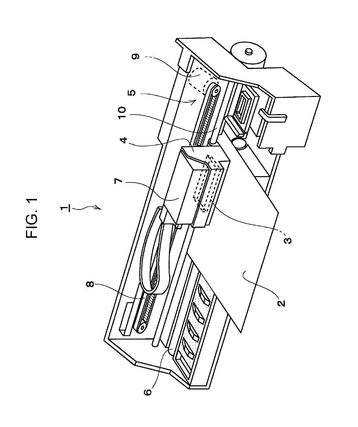
[0042]Exemplary embodiments of the invention will be described hereinafter with reference to the accompanying drawings. Although in the following exemplary embodiments, various limitations are described as preferred concrete examples of the invention, such examples of limitations do not actually limit the scope of the invention unless particular limitation of the invention is stated in the following description. The following description will be made in conjunction with an ink jet type printer (hereinafter, referred to simply as printer) 1 that is a kind of a liquid ejecting apparatus and an ink jet type recording head (hereinafter, referred to simply as recording head) 3 that is a kind of a liquid ejecting head mounted in the printer 1, which are mere examples.

[0043]FIG. 1 is a perspective view illustrating an internal configuration of the printer 1. The printer 1 is an apparatus that records an image or the like on a surface of a recording medium 2 (a kind of landing target), such...


PUM


Abstract

A liquid ejecting head includes a head body, a first member that has a first surface and a second surface and that holds the head body, a second member that has a third surface and that is adhered to the first surface by a first adhesive so that the third surface is along planar directions of the second surface, and a third member that is disposed so as to extend over the second surface and the third surface and that is adhered to the second surface and the third surface by a second adhesive. At an intersection portion at which the first adhesive and the second adhesive contact, an adhesive receiving portion that accepts inflow of at least one of the first adhesive and the second adhesive is formed.

Description

BACKGROUND1. Technical Field[0001]The present invention relates to a liquid ejecting head that includes three members adhered by adhesive, a liquid ejecting apparatus, and a production method for the liquid ejecting head.2. Related Art[0002]A liquid ejecting apparatus includes a liquid ejecting head and is capable of ejecting various kinds of liquids from the ejecting head. Examples of the liquid ejecting apparatus include image recording apparatuses, such as ink jet type printers and ink jet type plotters. The liquid ejecting apparatus is capable of accurately landing very small amounts of liquid at predetermined locations and, because of this advantage, is recently applied to various production apparatuses as well. For example, the liquid ejecting apparatus is applied to display production apparatuses that produce color filters of liquid crystal displays and the like, electrode forming apparatuses that form electrodes of organic electroluminescence (EL) displays, field emission di...

Claims


Application Information

Patent Timeline
Patent Type & Authority Patents(United States)
IPC IPC(8): B41J2/16B41J2/14
CPCB41J2/1607B41J2/14233B41J2/14274B41J2/1623B41J2/161B41J2002/14491B41J2002/14362B41J2002/14419B41J2/045B41J2/14
Inventor KINOSHITA, TOMOO
Owner SEIKO EPSON CORP
Why Eureka
Try Eureka