Filter LED lamp arrangement

a technology of led lamps and filter lamps, applied in the direction of electroluminescent light sources, electric lighting sources, semiconductor lamp usage, etc., can solve the problems of low power factor, relatively high reactive power, failure of the entire luminaire, etc., and achieve good lighting performan

Active Publication Date: 2019-07-02
SILICON HILL
View PDF11 Cites 11 Cited by
  • Summary
  • Abstract
  • Description
  • Claims
  • Application Information

AI Technical Summary

Benefits of technology

[0010]It is therefore an object of the invention to provide an LED lamp which has good lighting performance when fitted in a variety of lumin

Problems solved by technology

An undesirable result is a relatively low power factor and relatively high reactive power.
In some cases, a straightforward replacement of a florescent lamp by an LED lamp

Method used


Image

  • Filter LED lamp arrangement
  • Filter LED lamp arrangement
  • Filter LED lamp arrangement

Examples


Embodiment Construction

[0028]The following is a more detailed explanation of exemplary embodiments of the invention.

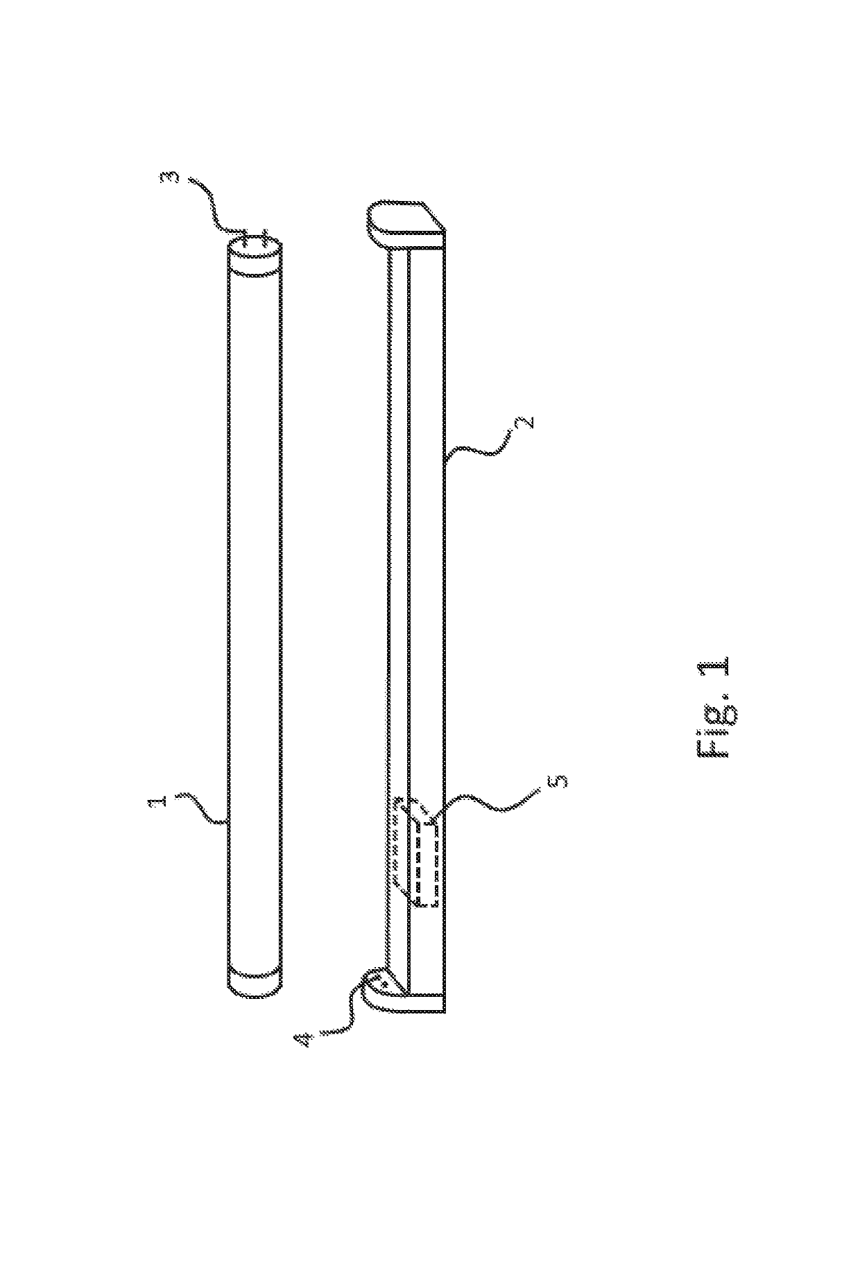
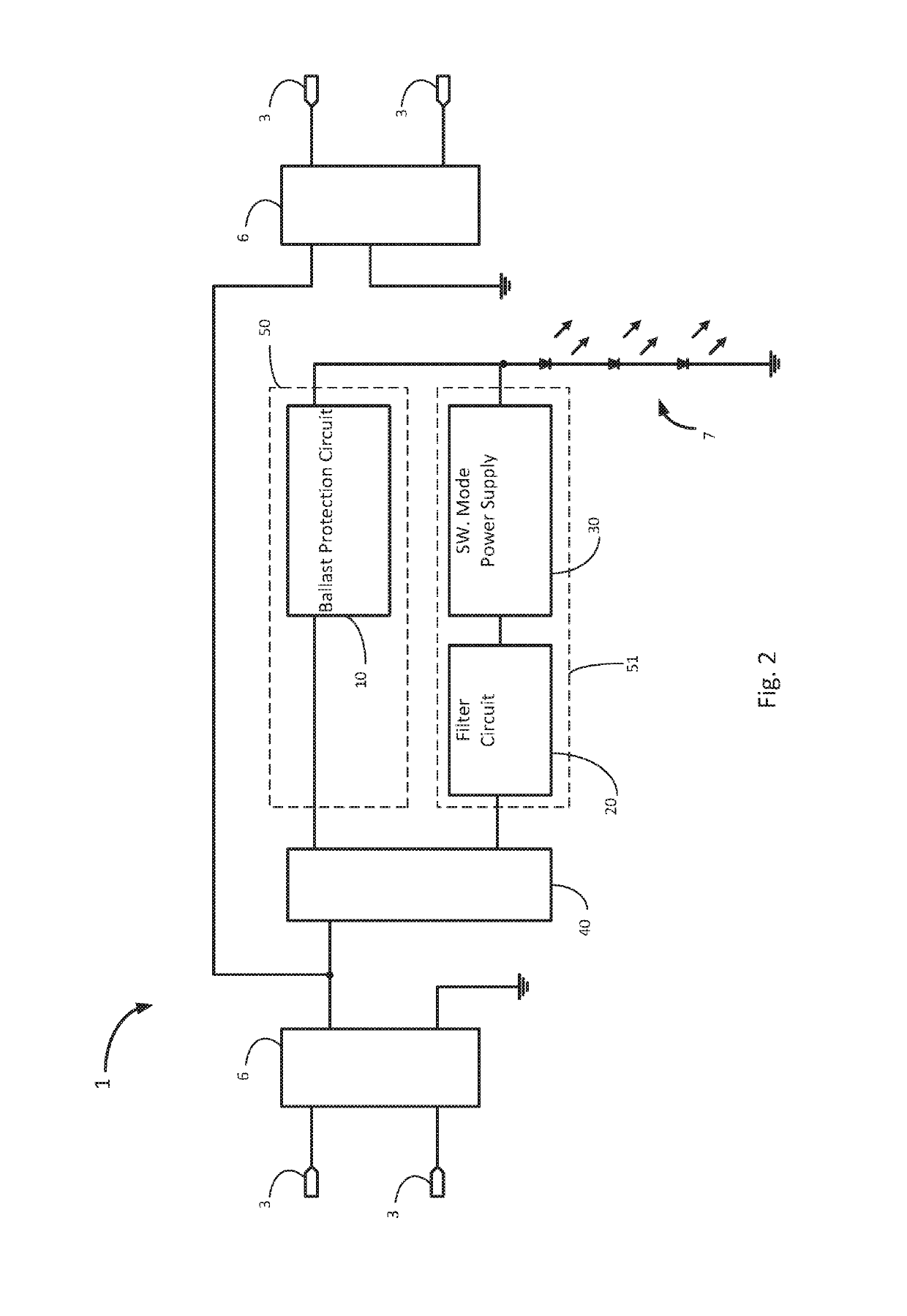
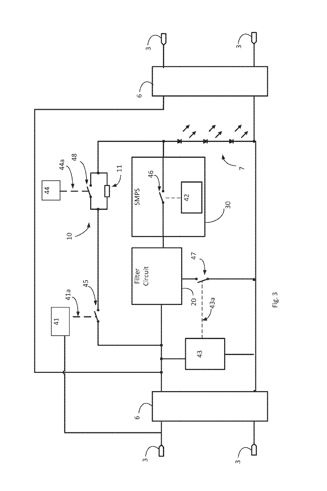
[0029]FIG. 1 is a diagram of an embodiment of the invention. The LED lamp 1 is configured to be compatible with a luminaire 2 designed for a fluorescent tube, the LED lamp preferably having the same length and shape as a standard fluorescent tube to enable the LED lamp 1 to fit into the luminaire without modification. Two electrical connectors 3 (usually in the form of pins) are provided at each end of the LED lamp 1, for releasably connecting to corresponding connectors 4 of the luminaire. The luminaire 2 may include a ballast 5 or may have no ballast. The ballast 5, if included in the luminaire, may be a magnetic ballast, an electronic ballast which operates as a constant current ballast, or an electronic ballast which operates as a constant power ballast.

[0030]The luminaire 2 provides electrical power to the LED lamp 1 via the connectors 4. The electrical power provided by the luminaire 2...


PUM


Abstract

An LED lamp suitable for use in a luminaire, the LED lamp adapted for receiving electrical power from the luminaire and comprising: one or more LEDs; a ballast protection circuit including an impedance; a filter circuit; a switched-mode power supply for driving the LEDs; one or more sensing circuits for generating at least one output, in dependence on whether the electrical power received from the luminaire indicates that the electrical power is generated via a magnetic ballast, an electronic ballast which operates as a constant current ballast, an electronic ballast which operates as a constant power ballast, or not via a ballast; and a plurality of switches for defining a plurality of operation modes of the LED lamp, and for switching among the plurality of operation modes in dependence on the at least one output of the sensing circuits.

Description

TECHNICAL FIELD[0001]The invention relates generally to light emitting diode (LED) lamps and LED lighting, and more particularly to LED lamps suitable to replace a fluorescent lamp in a luminaire having a ballast for use with fluorescent lamps.BACKGROUND[0002]Fluorescent lighting has been around for many years now. This form of lighting started out as a highly efficient alternative for incandescent light bulbs, but has recently been surpassed by LED lighting in terms of efficiency and power consumption, and also in other aspects as set out below.[0003]Fluorescent lamps generally comprise a tube filled with an inert gas and a small amount of mercury, capped at both ends with double pinned end caps. The end caps contain a glow wire to preheat the gasses inside the tube and to vaporize the mercury in order to assist with ignition of the fluorescent lamp. After the user turns on a main switch (e.g. a wall switch or a cord switch on the ceiling), the fluorescent lamp is ignited, and heat...

Claims


Application Information

Patent Timeline
IPC IPC(8): H05B33/08H05B37/02H05B44/00
CPCH05B33/089H05B33/0815Y02B20/30H05B45/3725H05B47/20
Inventor ROY, SHOUNAKDEKKER, MARTIJN JEROEN
Owner SILICON HILL
Why Eureka
Try Eureka