Rotatable bracket structure

a technology of rotatable brackets and brackets, which is applied in the field of rotatable bracket structures, can solve the problems of increasing production costs, inconvenient construction operation, and increasing difficulty, and achieves the effect of convenient and quick, convenient and quick, and rotatabl

Inactive Publication Date: 2019-07-09
GOLD CLASSIC ENTERPRISE
View PDF10 Cites 0 Cited by
  • Summary
  • Abstract
  • Description
  • Claims
  • Application Information

AI Technical Summary

Benefits of technology

[0003]The main object of the present invention is to provide a rotatable bracket structure, allowing the assembly of a hanging frame to be more convenient and quick and not to be limited by construction space, and capable of in combination with rod bodies of different diameters.
[0004]To achieve the object mentioned above, the present invention proposes a rotatable bracket structure, including a frame body and a fixation seat in connection with the frame body, where the frame body is configured with an engagement portion, and the fixation seat a sleeve, the inside of the fixation seat configured with a unidirectional rotating structure having an axle shaft allowed to be fixed to the engagement portion after passed through the sleeve, Furthermore, an elastic element is put around the axle shaft and positioned between the unidirectional rotating structure and sleeve. Whereby, the two fixation seats, upon assembly, are fixed to a wall surface, and the two frame bodies are properly rotated an angle to allow the two frame bodies to clamp and position a rod body through the unidirectional rotating structure to form a hanging frame after the two ends of the rod body are passed through the respective frame bodies, thus allowing the assembly of the hanging frame to be more convenient and quick.
[0005]According to the rotatable bracket structure, the unidirectional rotating structure comprises a ratchet ring configured inside the fixation seat and a volute button bar portion having an axle shaft, the ratchet ring is configured with a continuously arranged ratchet teeth, the volute button bar portion a plurality of button bars in a volute arrangement, the volute button bar portion is positioned on an inner surface of the rear cover of the fixation seat, whereby, when the volute button bar portion is rotated forward, the volute button bar portion is rotatable smoothly since the button bars are slidable along inclined faces of the ratchet teeth, and when the volute button bar portion is rotated reversely, the volute button bar portion is unable to be rotated since the button bars are stuck in included angles between the two adjacent ratchet teeth, thus achieving a one-way rotation effect.

Problems solved by technology

Since the two conventional brackets respectively are a fixed type on the assembly, they are not only very inconvenient in the construction operation but further increase the difficulty of it if the space for the construction is too narrow.
In addition, the conventional bracket is designed with the diameter of the diameter of the rod body such that manufacturers must make the rod brackets of different sizes to match with the rod bodies of different diameters, which not only increases the production cost but has the pressure of stock material.

Method used


Image

  • Rotatable bracket structure
  • Rotatable bracket structure
  • Rotatable bracket structure

Examples


Embodiment Construction

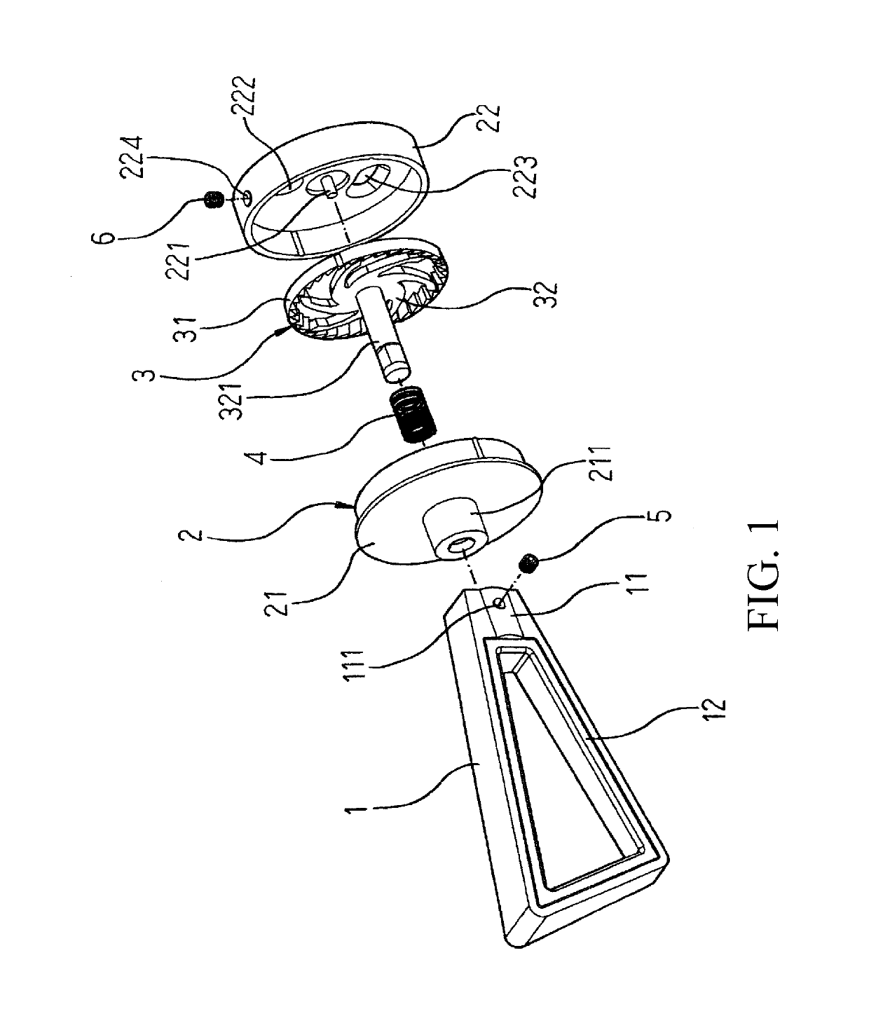
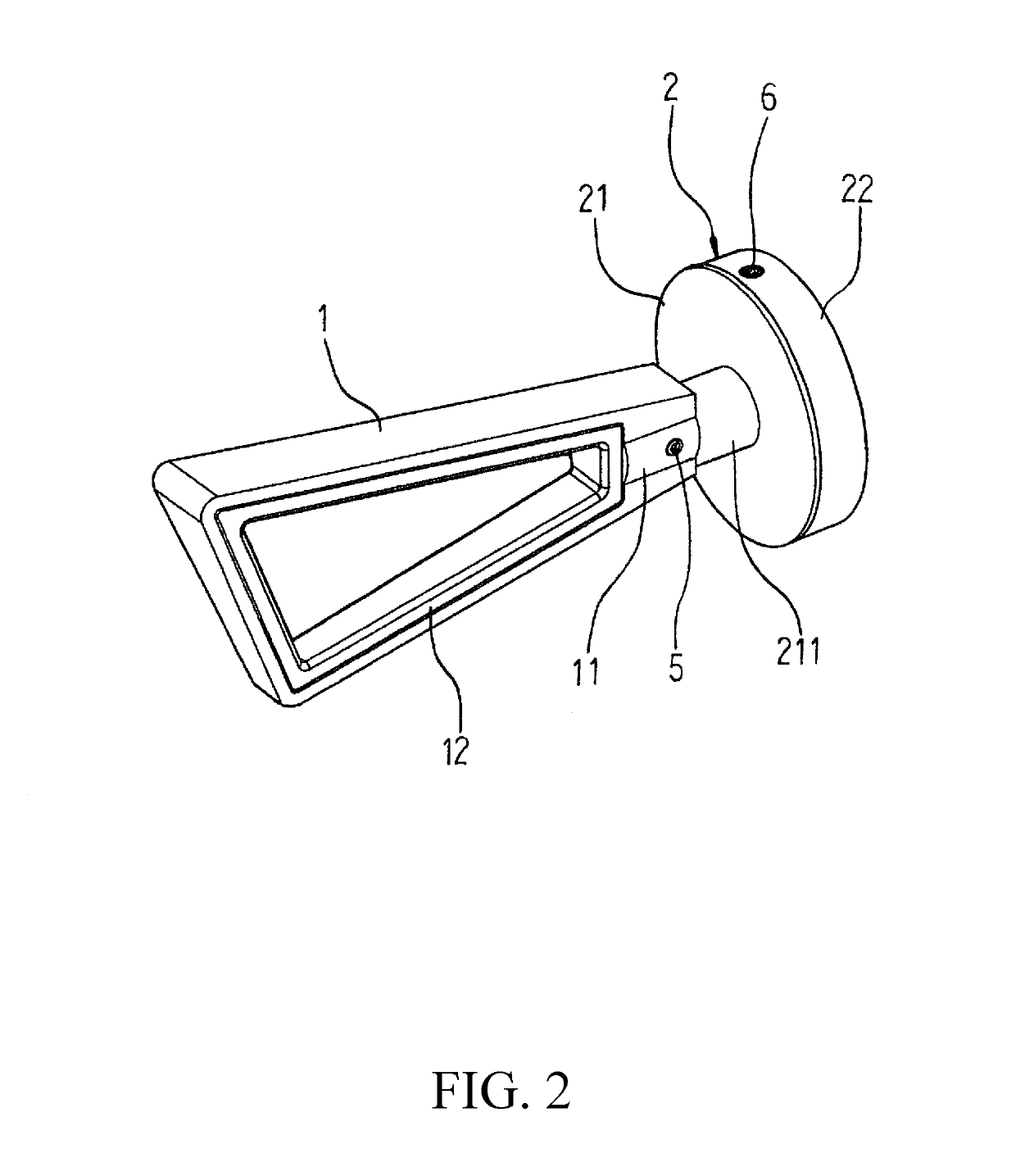
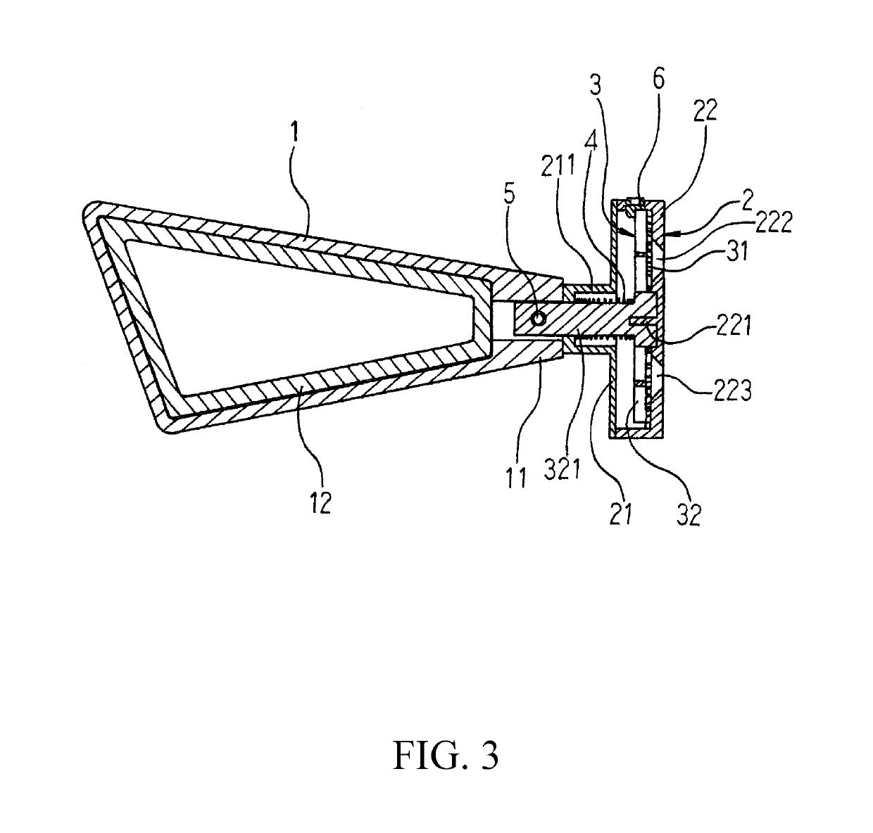
[0013]Referring to FIGS. 1, 2 and 3, a rotatable bracket structure of the present invention includes a frame body 1 and a fixation seat 2 in connection with the frame body 1, where the frame body 1 is a probably trapezoidal body, one end of which is configured with an engagement portion 11 having a fixation hole 111, and the inner edge of which is configured with a rubber element 12. The fixation seat 2 includes a front cover 21 and rear cover 22, where the front cover 21 is configured with a cylindrical sleeve 211, and the center of inner surface of the rear cover 22 a positioning rod 221. Furthermore, positioning holes 222, 223 are respectively configured at the two sides of the positioning rod 221 and a fixation hole 224 is configured on the peripheral of the rear cover 22.

[0014]A unidirectional rotating structure 3 is configured inside of the fixation seat 2. In the embodiment, the unidirectional rotating structure 3 includes a ratchet ring 31 configured inside the fixation seat...


PUM


Abstract

A rotatable bracket structure includes a frame body and a fixation seat in connection with the frame body, where the frame body is configured with an engagement portion, and the fixation seat a sleeve, the inside of the fixation seat configured with a unidirectional rotating structure having an axle shaft allowed to be fixed to the engagement portion after passed through the sleeve, Furthermore, an elastic element is put around the axle shaft and positioned between the unidirectional rotating structure and sleeve. Whereby, the two fixation seats, upon assembly, are fixed to a wall surface, and the two frame bodies are properly rotated an angle to allow the two frame bodies to clamp and position a rod body through the unidirectional rotating structure to form a hanging frame after the two ends of the rod body are passed through the respective frame bodies, thus achieving a convenient, quick assembly.

Description

TECHNICAL FIELD OF THE INVENTION[0001]The present invention relates to a rotatable bracket structure, and more particularly to a rotatable bracket structure, allowing the assembly of a hanging frame to be more convenient and not subject to the limitation of construction space constraints.DESCRIPTION OF THE PRIOR ART[0002]Hanging frames for the hanging of curtain cloth, towels, clothes and the like are usually be configured with two symmetrical brackets. Upon assembly construction of a hanging frame, one of the two brackets is first fixed on a wall surface, a rod body is passed through the bracket and another identical bracket, and the two brackets are then respectively fixed on the wall surface, or a rod body is first passed through the two brackets, and the two brackets are respectively fixed on the wall surface. Since the two conventional brackets respectively are a fixed type on the assembly, they are not only very inconvenient in the construction operation but further increase t...

Claims


Application Information

Patent Timeline
Patent Type & Authority Patents(United States)
IPC IPC(8): A47B96/07A47K10/04A47H1/102
CPCA47B96/07A47K10/04A47H1/102A47H1/142A47H1/122A47H1/14A47K10/10
Inventor CHENG, CHUNG-YING
Owner GOLD CLASSIC ENTERPRISE
Why Eureka
Try Eureka