State transitioning method and electronic device using the same

a state transition and electronic device technology, applied in the field of state transitioning methods, can solve the problems of unclear how to process the tradeoff between network burden and ue power consumption

Active Publication Date: 2019-07-16
ACER INC
View PDF10 Cites 5 Cited by
  • Summary
  • Abstract
  • Description
  • Claims
  • Application Information

AI Technical Summary

Problems solved by technology

Moreover, it is unclear how to process the tradeoff between network burdens and UE power consumptions.

Method used


Image

  • State transitioning method and electronic device using the same
  • State transitioning method and electronic device using the same
  • State transitioning method and electronic device using the same

Examples


Embodiment Construction

[0039]Reference will now be made in detail to the present exemplary embodiments of the disclosure, examples of which are illustrated in the accompanying drawings. Wherever possible, the same reference numbers are used in the drawings and the description to refer to the same or like parts.

[0040]Considering the above described uncertainties, the subsequent disclosure provides an overview of proposed concepts and then various exemplary embodiments.

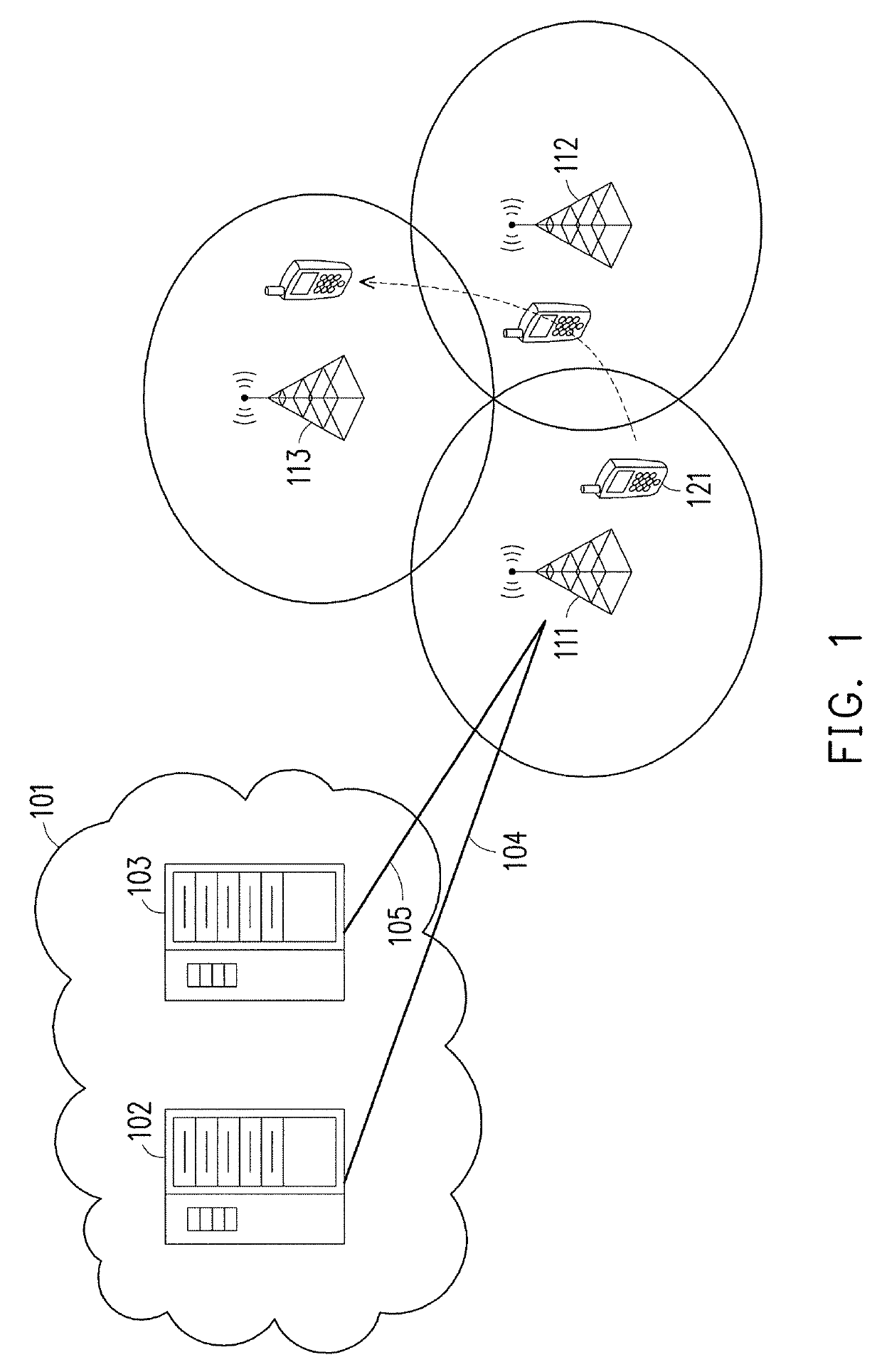
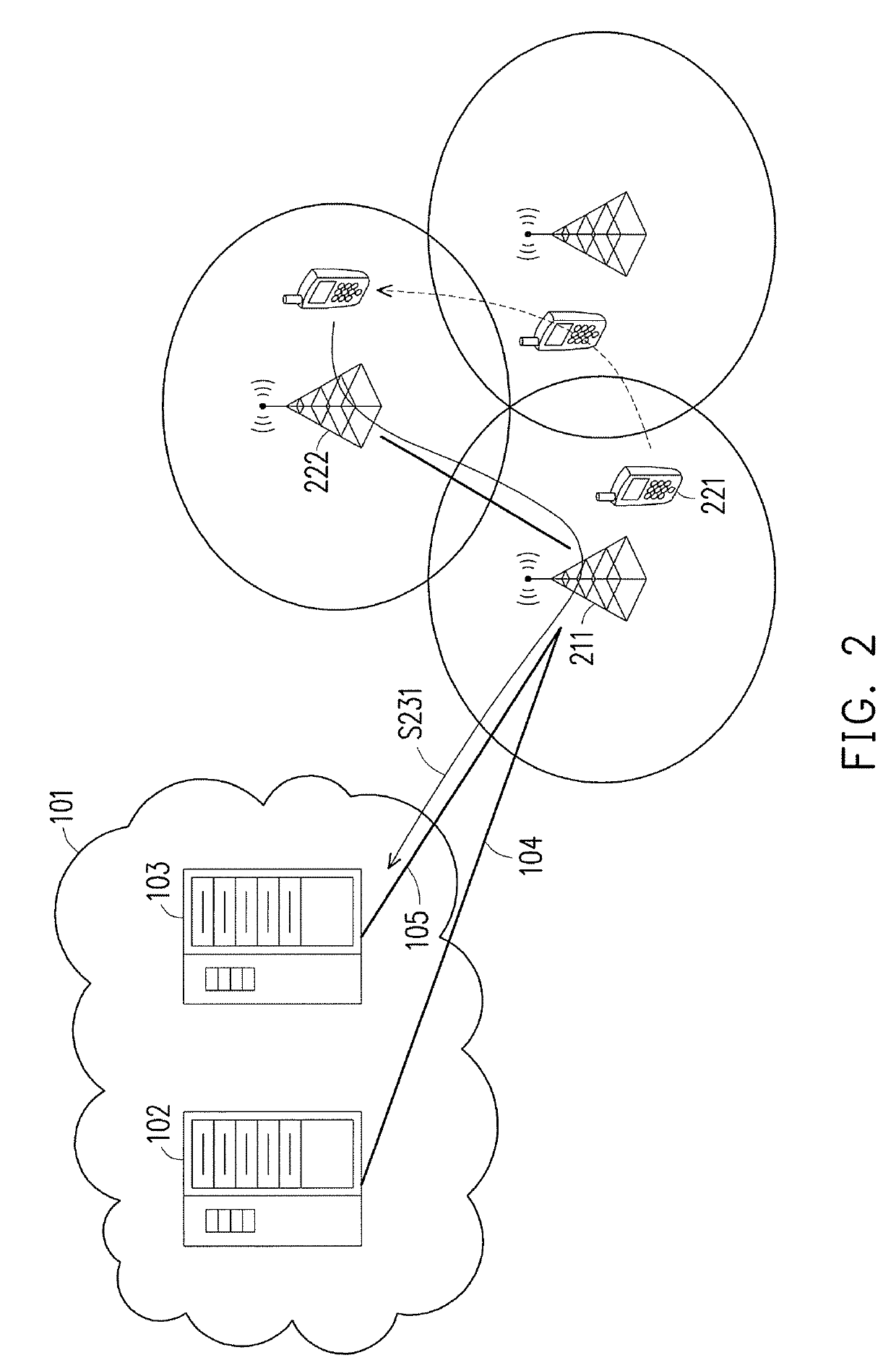
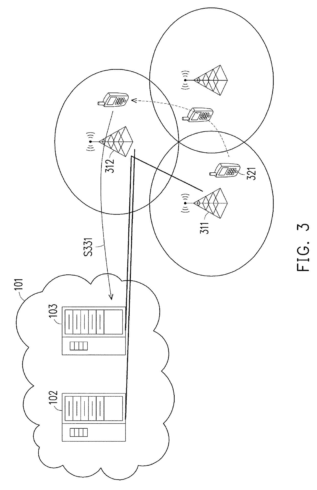
[0041]One issue is that whether and when a UE should be configured to enter the RRC inactive state is uncertain from the network point of view. Also, how to arrange the RAN-based notification area for a UE may also needed to be considered. For a UE in the RRC inactive state, multiple connecting nodes would need to keep the UE identity as well as its context and / or configuration for a period. The Anchor node would need to also maintain the connection of both CP and UP between the NG-RAN and the CN.

[0042]For example, for a UE intending to imple...


PUM


Abstract

The disclosure is directed to a state transitioning method for switching between a connected state and an inactive state and related apparatuses using the same. In one of the exemplary embodiments, the disclosure is directed to a state transitioning method used by a user equipment (UE) for switching between a connected state and an inactive state. The method would include not limited to: establishing a wireless connection to enter into a connected state; receiving an inactive state command while being in the connected state; entering into the inactive state in response to receiving the inactive state command; transmitting a connection resume request while being in the inactive state; receiving an uplink (UL) grant which corresponds to the connection resume request; and transmitting UL data in response to receiving the UL grant.

Description

CROSS-REFERENCE TO RELATED APPLICATION[0001]This application claims the priority benefit of U.S. provisional application Ser. No. 62 / 401,174, filed on Sep. 29, 2016. The entirety of the above-mentioned patent application is hereby incorporated by reference herein and made a part of this specification.TECHNICAL FIELD[0002]The disclosure is directed to a state transitioning method for switching between a connected state and an inactive state, a user equipment using the same, and a base station using the same.BACKGROUND[0003]One of the important key performance indicators of new radio (NR) technology is control plane latency from a power efficient state to a data transmission state. Preferably, the latency would be less than 10 milliseconds. For NR, a new radio resource control (RRC) state has been introduced to satisfy the above described purpose. Conventionally, RRC states include a RRC connected state during which an electronic device is connected to the network and a RRC idle state...

Claims


Application Information

Patent Timeline
Patent Type & Authority Patents(United States)
IPC IPC(8): H04W52/02H04W76/27
CPCH04W76/27H04W52/028H04W52/0222Y02D70/26Y02D70/142Y02D70/144Y02D70/20Y02D70/00Y02D30/70
Inventor CHEN, HUNG-CHEN
Owner ACER INC
Why Eureka
Try Eureka