
Localization and mapping method

a mapping and localization technology, applied in image enhancement, image data processing, instruments, etc., can solve the problems of 3d-2d correspondences and prior art methods that do not provide satisfying efficiency

Active Publication Date: 2019-07-30
NOKIA TECHNOLOGLES OY
View PDF15 Cites 0 Cited by
  • Summary
  • Abstract
  • Description
  • Claims
  • Application Information

AI Technical Summary

Benefits of technology

The patent describes a method for finding a match between two images. The method involves using a hash key to compare the images and finding the closest match. The method also includes a way to minimize the cost of finding a match by selecting the right bit of the hash key. Overall, the method improves the speed and accuracy of finding matches between images.

Problems solved by technology

Since the camera pose can be estimated using correspondences between 3D points in the map and 2D features in the image, the key problem in the relocalization is to obtain the 3D-2D correspondences.
However, in SLAM relocalization real time performance is of critical importance, and due to the vast amount of data to be processed, the prior art methods do not provide satisfying efficiency.

Method used


Image

  • Localization and mapping method
  • Localization and mapping method
  • Localization and mapping method

Examples


Embodiment Construction

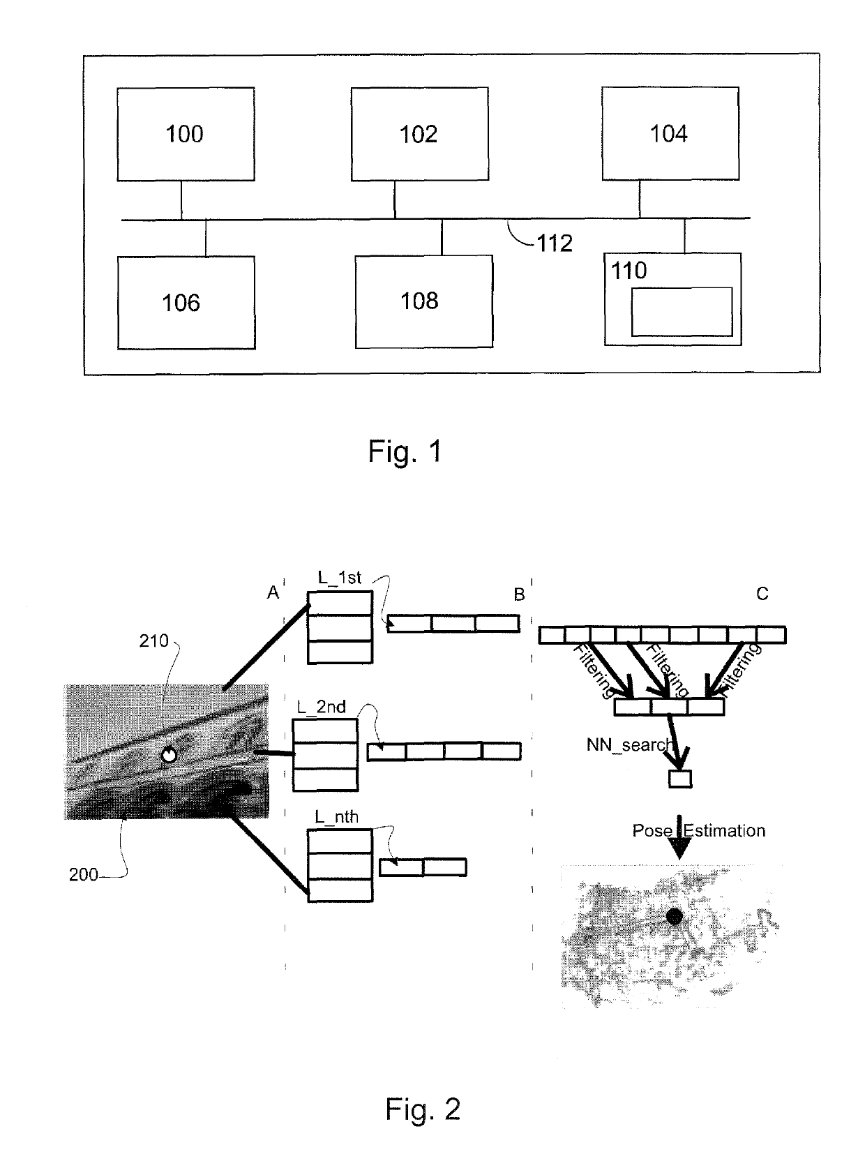
[0026]FIG. 1 shows a computer graphics system suitable to be used in image processing, for example in 3D point cloud analysis process according to an embodiment. The generalized structure of the computer graphics system will be explained in accordance with the functional blocks of the system. For a skilled man, it will be obvious that several functionalities can be carried out with a single physical device, e.g. all calculation procedures can be performed in a single processor, if desired. A data processing system of an apparatus according to an example of FIG. 1 includes a main processing unit 100, a memory 102, a storage device 104, an input device 106, an output device 108, and a graphics subsystem 110, which all are connected to each other via a data bus 112.

[0027]The main processing unit 100 is a conventional processing unit arranged to process data within the data processing system. The memory 102, the storage device 104, the input device 106, and the output device 108 are con...


PUM


Abstract

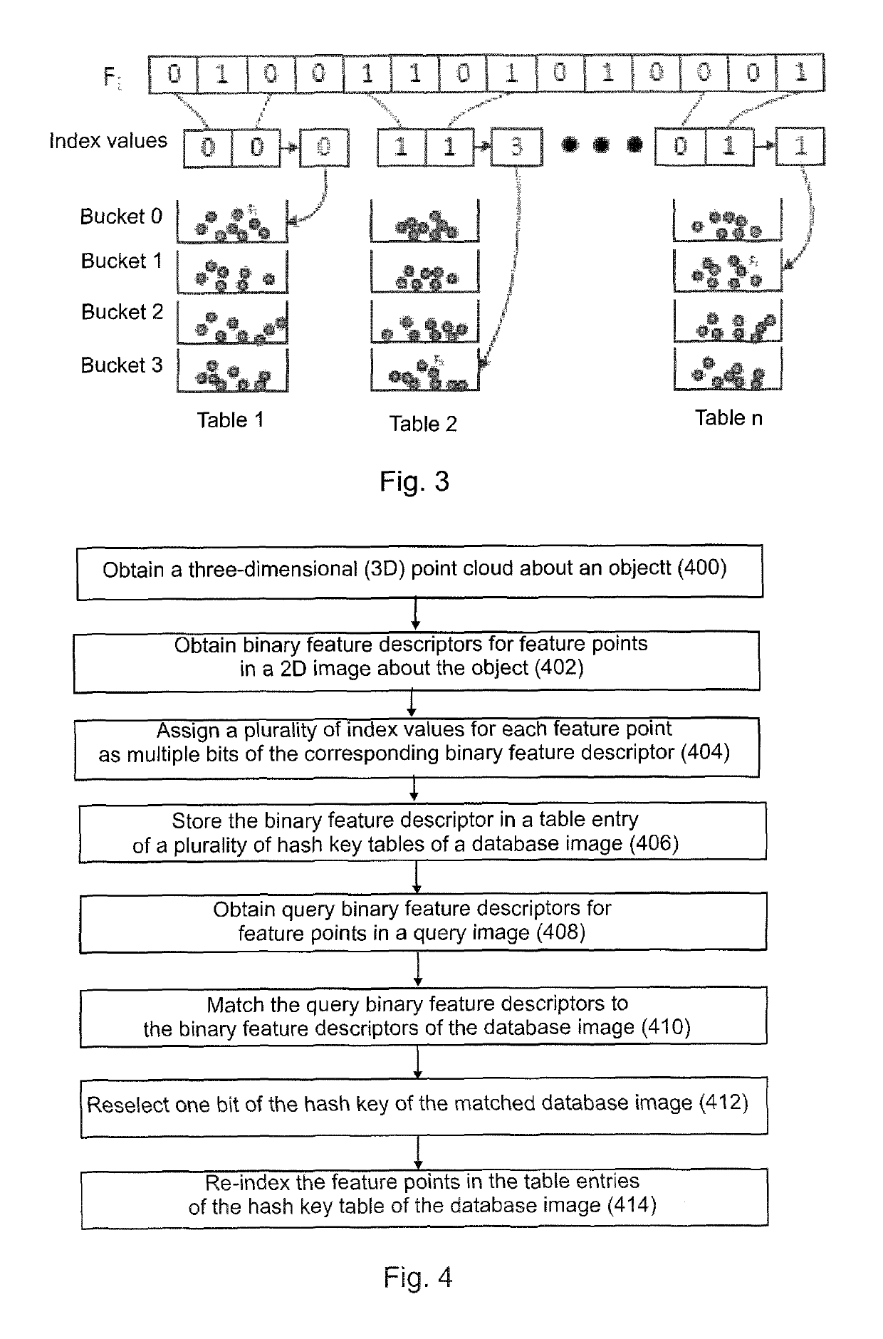
A method comprising: obtaining a three-dimensional (3D) point cloud about an object; obtaining binary feature descriptors for feature points in a 2D image about the object; assigning a plurality of index values for each feature point as multiple bits of the corresponding binary feature descriptor; storing the binary feature descriptor in a table entry of a plurality of hash key tables of a database image; obtaining query binary feature descriptors for feature points in a query image; matching the query binary feature descriptors to the binary feature descriptors of the database image; reselecting one bit of the hash key of the matched database image; and re-indexing the feature points in the table entries of the hash key table of the database image.

Description

RELATED APPLICATION[0001]This application was originally filed as Patent Cooperation Treaty Application No. PCT / CN2015 / 071607 filed Jan. 27, 2015.FIELD OF THE INVENTION[0002]The present invention relates to image processing, and more particularly to simultaneous localization and mapping of point clouds.BACKGROUND OF THE INVENTION[0003]3D point clouds are used in various image processing and computer vision applications. 3D point clouds are sets of data points in a 3D coordinate system typically representing an external surface of an object. A large number of points are measured on the surface of an object, and the obtained point cloud may be stored in a file. For computer vision applications, the 3D points are typically mapped to a recognized feature of a 2D image of the object.[0004]Simultaneous localization and mapping (SLAM) has been extensively studied in both robotics and computer vision. SLAM refers to a problem of updating a map of an unknown environment while simultaneously ...

Claims


Application Information

Patent Timeline
Patent Type & Authority Patents(United States)
IPC IPC(8): G06K9/46G06F16/583G06K9/62G06T7/246G06T7/33G06K9/00
CPCG06K9/4671G06F16/583G06K9/00214G06K9/6293G06T7/246G06T7/33G06K9/00664G06T2207/30244G06V20/653G06V20/10G06V10/462G06V10/811G06F18/256
Inventor FAN, LIXINFENG, YOUJIWU, YIHONG
Owner NOKIA TECHNOLOGLES OY
Learn More