
Timepiece mechanism, timepiece movement and timepiece having such a mechanism

a timepiece movement and mechanism technology, applied in the field of timepiece mechanisms, can solve the problems of increasing increasing the cost of the mechanism, and reducing so as to limit the thickness of the timepiece movement and limit the cost and energy loss

Active Publication Date: 2019-08-06
LVMH SWISS MFG SA
View PDF12 Cites 4 Cited by
  • Summary
  • Abstract
  • Description
  • Claims
  • Application Information

AI Technical Summary

Benefits of technology

The present invention aims to reduce costs and energy losses in a time piece by integrating both the regulator and escapement mechanisms onto the same plate of material. This eliminates the need for multiple layers of mechanisms and reduces friction, resulting in a thinner timepiece movement.

Problems solved by technology

Usual timepiece movements are very complicated mechanisms which include a large number of moving parts, which makes such mechanisms costly, energy consuming because of friction undergone by moving parts.
Further, these usual mechanisms are relatively bulky because they are constituted by a stack of different timepiece mechanisms, usually at least mainspring, transmission, escapement mechanism and regulator.
Thus, this document tried to propose a solution for limiting the number of parts moving with friction; however, the problem of thickness of the timepiece movement remains.

Method used


Image

  • Timepiece mechanism, timepiece movement and timepiece having such a mechanism
  • Timepiece mechanism, timepiece movement and timepiece having such a mechanism
  • Timepiece mechanism, timepiece movement and timepiece having such a mechanism

Examples


Embodiment Construction

[0043]In the Figures, the same references denote identical or similar elements.

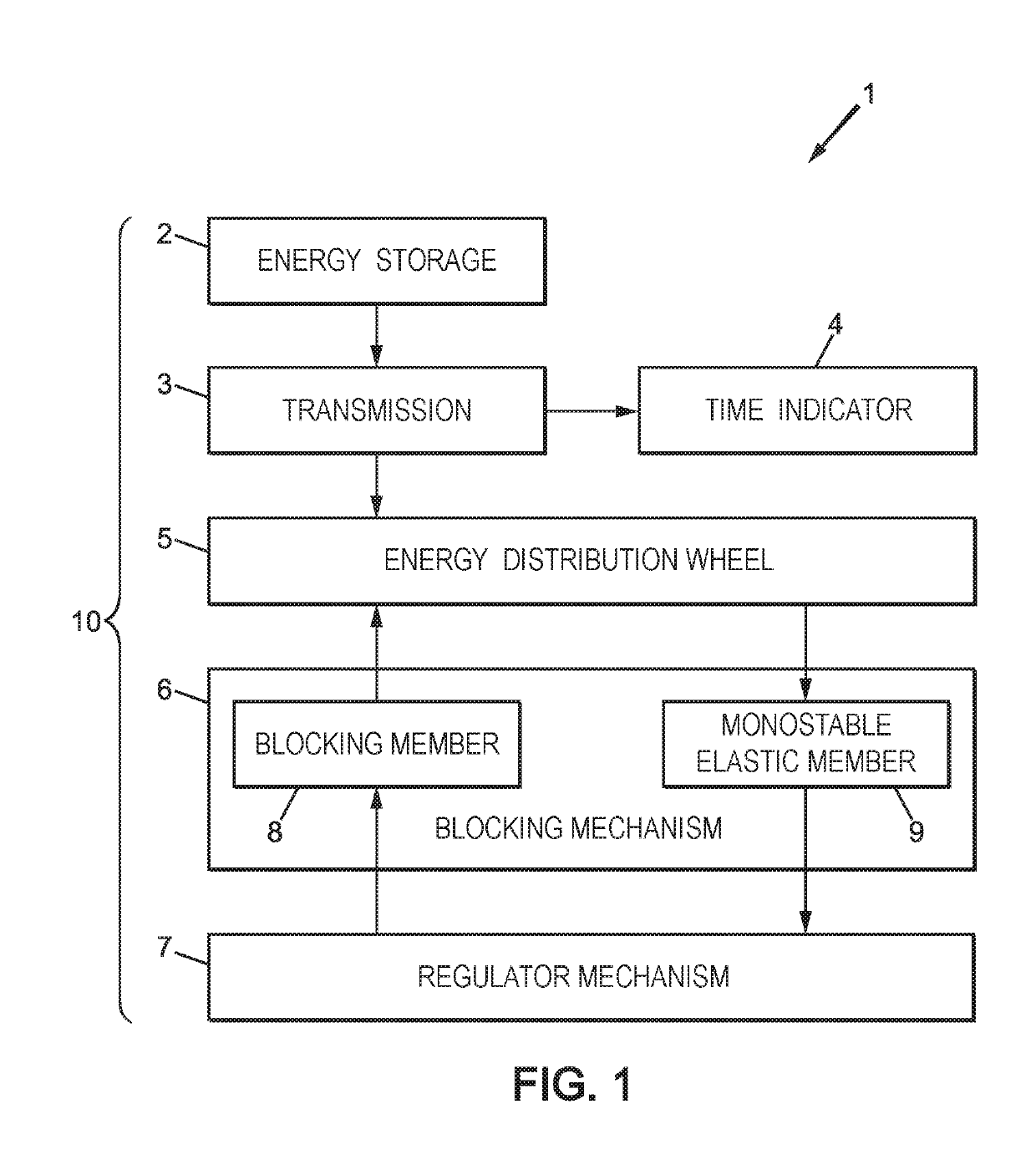
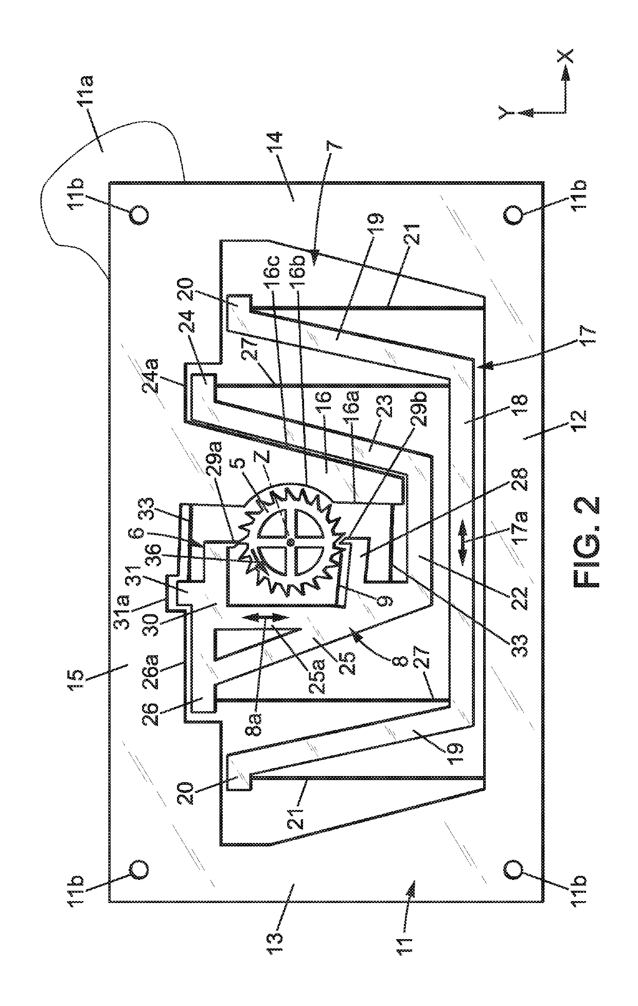
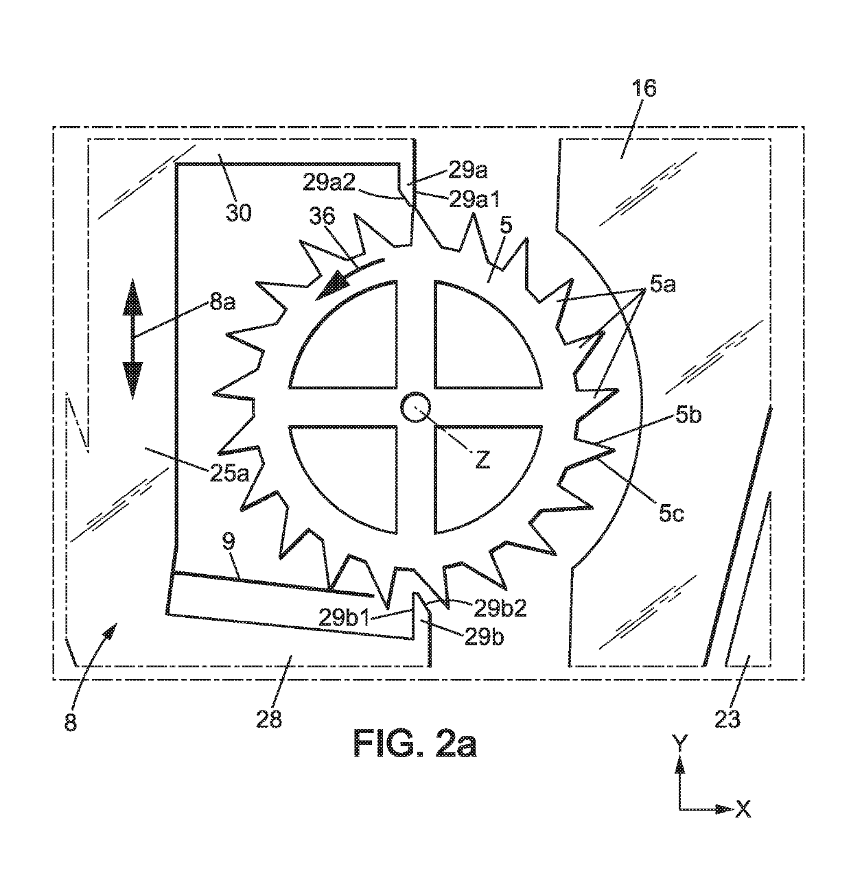
[0044]FIG. 1 shows a schematic bloc diagram of a mechanical timepiece 1, for instance a watch, including at least the following:[0045]a mechanical energy storage 2;[0046]a transmission 3 powered by the energy storage 2;[0047]one or several time indicator(s) 4, for instance watch hands driven by the transmission 3;[0048]an energy distribution member 5 driven by the transmission 3;[0049]a blocking mechanism 6 having for instance a blocking member 8 adapted to sequentially hold and release the energy distribution member 5 so that said energy distribution member may move step by step according to a repetitive movement cycle, of a constant travel at each movement cycle;[0050]a regulator mechanism 7, which is an oscillating mechanism controlling the blocking mechanism to move it regularly in time so that the hold and release sequence of the blocking mechanism be of constant duration, thus giving the tempo of th...


PUM


Abstract

A monolithic timepiece mechanism made in a single plate of material, including a frame, a first elastic suspension and an inertial regulating member which is connected to the frame by the first elastic suspension so as to be able to oscillate, a blocking mechanism having a blocking member connected to the frame by a second elastic suspension. The blocking member is controlled by the regulating member to be able to regularly and alternatively hold and release a energy distribution member and to regularly transmit energy from the energy distribution member to the regulating member.

Description

CROSS-REFERENCE TO RELATED APPLICATION[0001]This application is a 35 USC § 371 US National filing of International Application No. PCT / EP2015 / 078865 filed Dec. 7, 2015, and claims priority under the Paris Convention to European Patent Application No. 14197017.8 filed on Dec. 9, 2014.FIELD OF THE DISCLOSURE[0002]The invention relates to timepiece mechanisms, to timepiece movements and timepieces having such mechanisms.BACKGROUND OF THE DISCLOSURE[0003]Usual timepiece movements are very complicated mechanisms which include a large number of moving parts, which makes such mechanisms costly, energy consuming because of friction undergone by moving parts. Further, these usual mechanisms are relatively bulky because they are constituted by a stack of different timepiece mechanisms, usually at least mainspring, transmission, escapement mechanism and regulator.[0004]Document US2013176829A1 proposed a monolithic timepiece mechanism made in a single plate of material, comprising a frame, a fi...

Claims


Application Information

Patent Timeline
Patent Type & Authority Patents(United States)
IPC IPC(8): G04B15/00G04B15/08G04B15/06G04B15/02G04B17/04G04B29/04G04B17/10
CPCG04B15/06G04B15/00G04B15/02G04B29/04G04B17/045G04B17/10G04B15/08
Inventor SEMON, GUYYPMA, WOUT JOHANNES BENJAMINTOLOU, NIMA
Owner LVMH SWISS MFG SA
Learn More