Permanent magnet motor

a permanent magnet and motor technology, applied in the direction of dynamo-electric machines, magnetic circuit rotating parts, magnetic circuit shape/form/construction, etc., can solve problems such as vibration and noise, and achieve the effect of reducing torque rippl

Active Publication Date: 2019-08-06
MITSUBISHI ELECTRIC CORP
View PDF15 Cites 0 Cited by
  • Summary
  • Abstract
  • Description
  • Claims
  • Application Information

AI Technical Summary

Benefits of technology

[0008]According to the permanent magnet motor of the present invention, the width of the connection portions and the size of the permanent magnets are adjusted, whereby a torque ripple can be reduced.

Problems solved by technology

This causes a torque ripple which leads to vibration and noise.

Method used


Image

  • Permanent magnet motor
  • Permanent magnet motor
  • Permanent magnet motor

Examples


embodiment 1

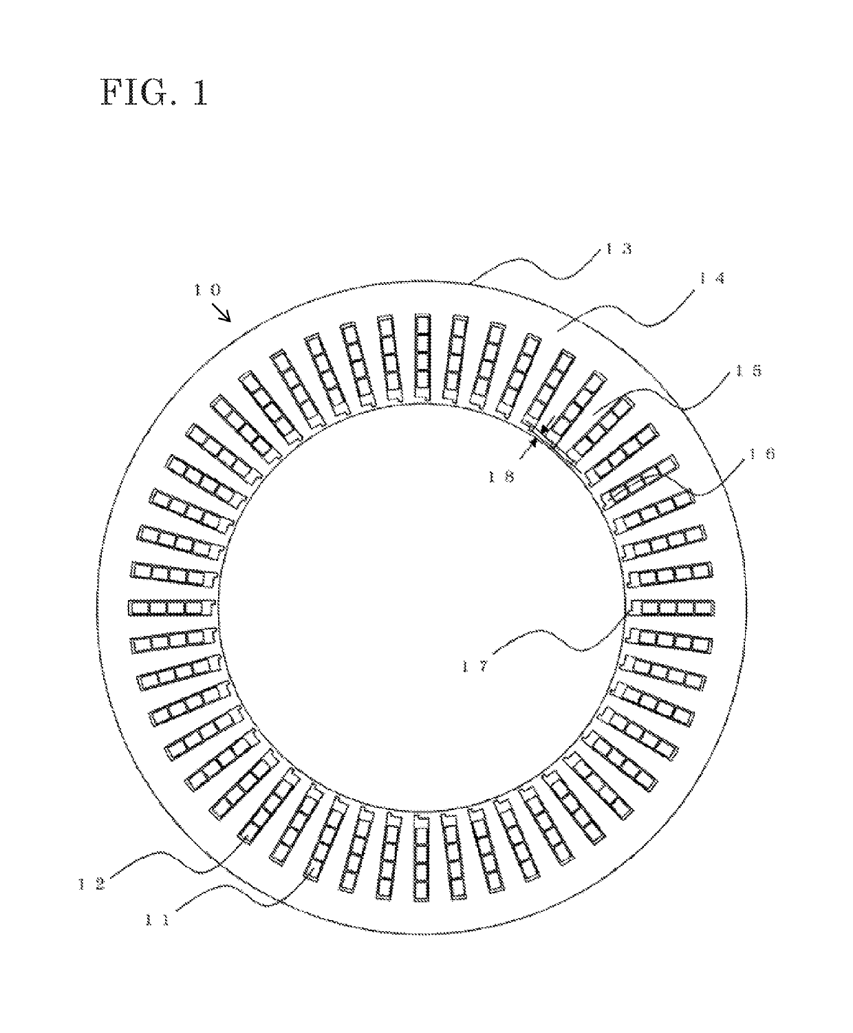
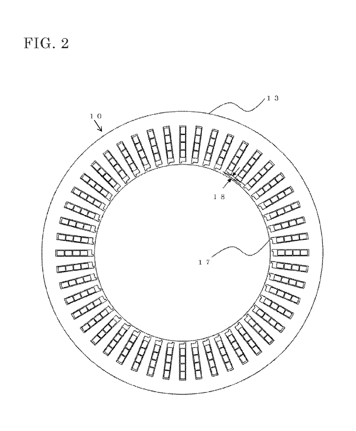
[0015]FIG. 1 is a cross-sectional view of a stator 10 of a permanent magnet motor according to embodiment 1 of the present invention. The stator 10 is formed of an armature winding 11, an armature winding 12, and a stator core 13.

[0016]The stator core 13 is formed by stacking, in the axial direction, core pieces which are fabricated by stamping a magnetic material such as an electromagnetic steel sheet. The stator core 13 includes an annular core back 14 and teeth 15 each extending inward in the circumferential direction from the core back 14. The armature windings 11, 12 are housed in slots 16 formed between the adjacent teeth 15. Insulating paper sheets (not illustrated), etc. are inserted between the armature windings 11, 12 and the stator core 13 forming the slots 16, so that electrical insulation is ensured.

[0017]The number of the teeth 15 formed is 48 in total. Accordingly, the number of the slots 16 formed is also 48. Four coils of the armature windings 11, 12 are housed in e...


PUM


Abstract

It has been discovered that torque ripples can be reduced by adopting a shape in which: the width of a shoe connection formed in a stator of a permanent magnet motor is equal to or smaller than the thickness of each of core pieces constituting a stator core; and a relationship of 0.7≤Wm / (Tm×Gm)≤3.3 is satisfied, where Wm is the length of the long side of a flat plate-shaped permanent magnet embedded in a rotor, Tm is the length of the short side of the permanent magnet, and Gm is the maximum distance from the outer circumference of the rotor to the permanent magnet.

Description

CROSS REFERENCE TO RELATED APPLICATIONS[0001]This application is a National Stage of International Application No. PCT / JP2015 / 077739, filed Sep. 30, 2015, the contents of which are incorporated herein by reference in its entirety.TECHNICAL FIELD[0002]The present invention relates to a permanent magnet motor, and more particularly, to a permanent-magnet embedded motor having a rotor with permanent magnets embedded therein.BACKGROUND ART[0003]In this type of a permanent-magnet embedded motor, a plurality of permanent magnets are embedded in a rotor so as to be adjacent to each other in the circumferential direction of the rotor. In each pair of the adjacent permanent magnets in the circumferential direction of the rotor, the magnetic poles thereof are different from each other. In the surrounding area of a portion where the magnetic poles of each pair of the adjacent permanent magnets are switched, an abrupt change in magnetic flux density occurs. This causes a torque ripple which lea...

Claims


Application Information

Patent Timeline
Patent Type & Authority Patents(United States)
IPC IPC(8): H02K21/12H02K1/27H02K21/14H02K1/16H02K29/03
CPCH02K1/274H02K1/16H02K21/14H02K29/03H02K1/27H02K2201/06H02K1/146H02K1/2706H02K2213/03
Inventor TAKIZAWA, YUJIAKUTSU, SATORUOKAZAKI, MASAFUMIAIDA, HIROSHIHIROTANI, YUITO, KAZUMASA
Owner MITSUBISHI ELECTRIC CORP
Why Eureka
Try Eureka