Rotor of rotary electric machine and rotary electric machine

Pending Publication Date: 2022-09-29
HONDA MOTOR CO LTD
View PDF0 Cites 0 Cited by
  • Summary
  • Abstract
  • Description
  • Claims
  • Application Information

AI Technical Summary

Benefits of technology

[0012]In the rotor of the rotary electric machine according to the above (1), the magnets are arranged such that the separation distances, between the two or more magnets per pole along the circumferential direction of the rotor, alternately vary every pole along the circumferential direction of the rotor, so that magnetisms of magnets of magnetic poles adjacent to each other in the circumferential direction of the rotor are alternately provided to be “large”, “small”, “large”, and “small”. Consequently, due to magnetic pole fluctuation of a coil caused by alternating current, maximum torques at maximum voltages in the magnetic poles adjacent to each other in the circumferential direction overlap each other at the “large” and “small” magnetisms, so that torque fluctuation occurring in the rotor during follow-up rotation can be suppressed, and torque ripple can be reduced. Therefore, the rotary electric machine capable of efficiently reducing torque ripple with a simple configuration can be provided. A plurality of types of stator coils do not have to be used, and the stator and rotor do not have to be specially processed, so that there is no concern of cos

Problems solved by technology

Therefore, there is a problem that a structure of a rotary electric machine is comp

Method used


Image

  • Rotor of rotary electric machine and rotary electric machine
  • Rotor of rotary electric machine and rotary electric machine
  • Rotor of rotary electric machine and rotary electric machine

Examples


first embodiment

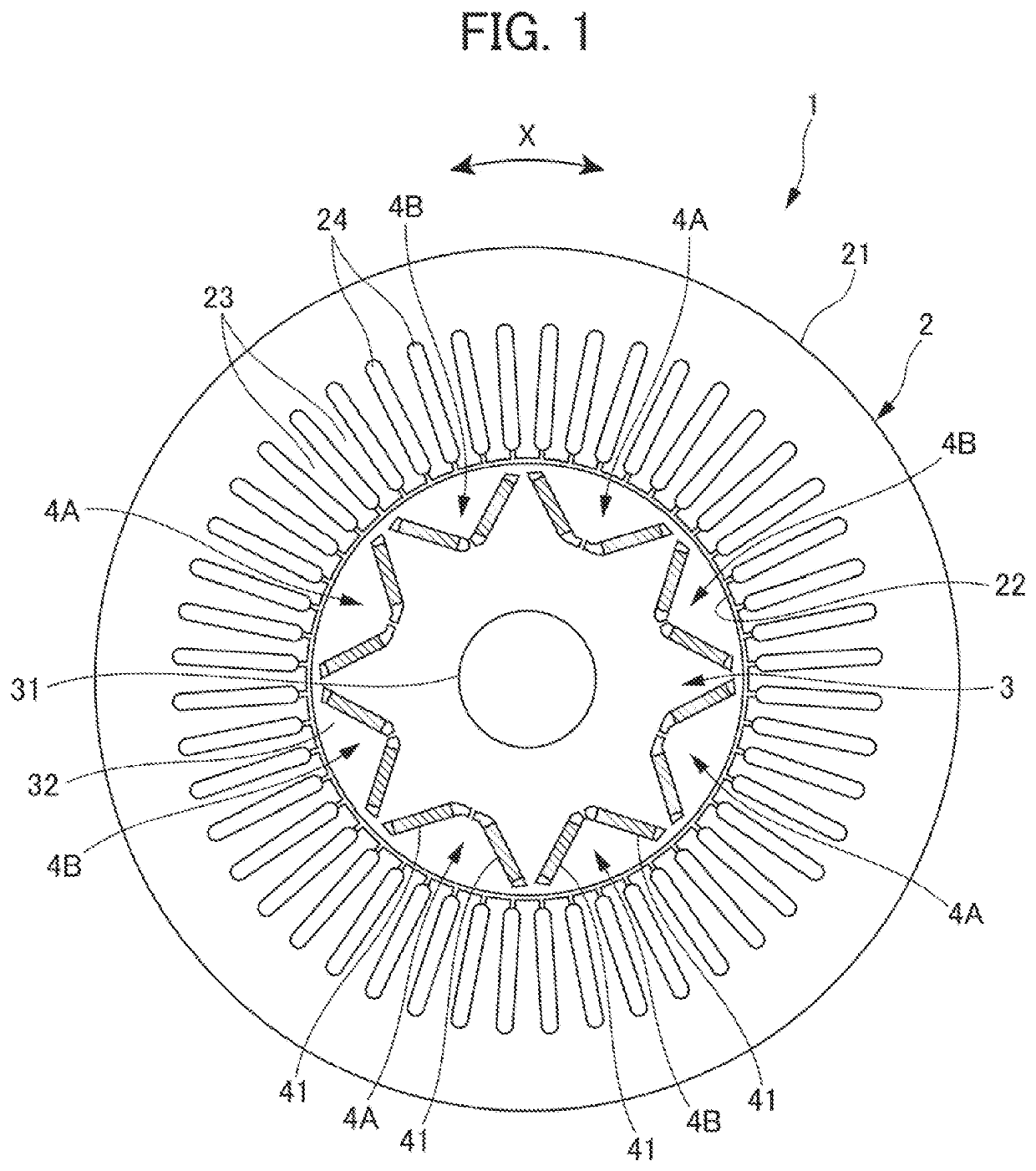
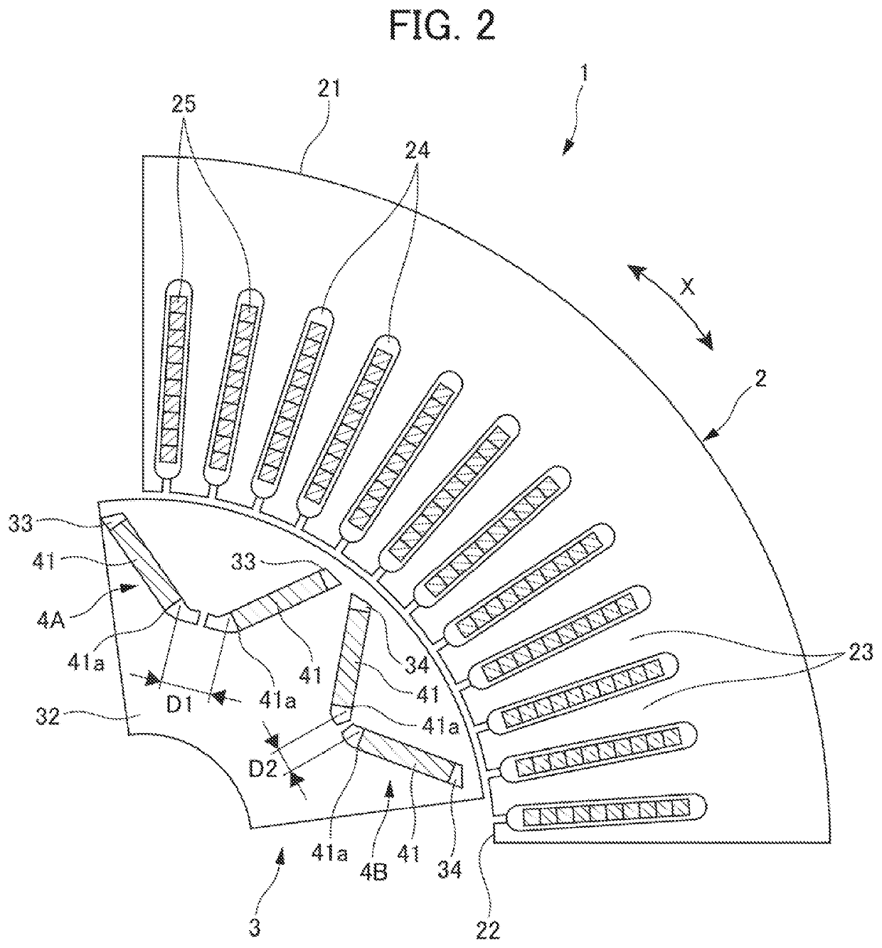
[0019]Hereinafter, description will be made in detail as to embodiments of the present invention with reference to the drawings. FIGS. 1 and 2 are cross-sectional views showing a rotary electric machine according to the present invention. A rotary electric machine 1 includes a stator 2 and a rotor 3.

[0020]The stator 2 includes, for example, a stator core 21 including a stacked body of a plurality of stacked thin core plates. The stator core 21 includes a shaft hole 22 penetrating a center in an axial direction, a plurality of teeth 23 arranged radially toward the shaft hole 22, and a plurality of slots 24 formed between teeth 23 and 23 adjacent to each other and opened toward the shaft hole 22. A coil 25 is inserted into each slot 24. FIG. 1 does not show any coils 25. Note that in the stator 2 and the stator core 21, as shown by arrows in FIGS. 1 and 2, an X-direction along which the slots 24 are arranged is a circumferential direction, and a vertical direction to a paper surface i...

second embodiment

[0028]In a rotor core 32 of the rotary electric machine 10 three magnet insertion holes 35 or 36 are provided per pole. The magnet insertion holes 35 are provided in a magnetic pole 4A, and the magnet insertion holes 36 are provided in a magnetic pole 4B. The magnet insertion holes 35 and 36 penetrate the rotor core 32 in an azial direction. The three magnet insertion holes 35 or 36 are arranged side by side in a circumferential direction of the rotor core 32. Two magnet insertion holes 35 or 36 are arranged on opposite sides of the magnet insertion hole 35 or 36 in a center of each magnetic pole 4A or 4B, respectively, such that outer ends of the holes in the circumferential direction deviate slightly outward in a radial direction. Magnets 42 are inserted into three magnet insertion holes 35 or 36 of each of the magnetic poles 4A and 4B. Consequently, three magnets 42 are arranged in each of the magnetic poles 4A and 4B.

[0029]Three magnets 42 of the magnetic pole 4A and three magn...


PUM


Abstract

Provided are a rotor of a rotary electric machine, and a rotary electric machine, in which torque ripple can be efficiently reduced with a simple configuration. In the rotor of the rotary electric machine which is rotatably disposed in a stator, and the rotary electric machine including the stator, and the rotor rotatably disposed in the stator, two or more magnets are arranged per pole, and arranged such that separation distances, between the two or more magnets per pole along a circumferential direction of the rotor, alternately vary every pole along the circumferential direction of the rotor.

Description

[0001]This application is based on and claims the benefit of priority from Japanese Patent Application No. 2021-052845, filed on 26 Mar. 2021, the content of which is incorporated herein by reference.BACKGROUND OF THE INVENTIONField of the Invention[0002]The present invention relates to a rotor of a rotary electric machine, and a rotary electric machine.Related Art[0003]In a hybrid car or an electric car, a rotary electric machine is mounted. It is known that in the rotary electric machine, torque ripple (torque pulsation) is generated and is one of factors of pulsation during low speed running, noise during high speed running and vibration.[0004]Conventionally, various attempts are made to reduce torque ripple of the rotary electric machine. For example, Patent Document 1 discloses that the attempts include alternately changing slot and coil shapes in a circumferential direction of a stator, forming salient pole portions of plural poles in a circumferential direction of a rotor, an...

Claims


Application Information

Patent Timeline
IPC IPC(8): H02K1/276H02K29/03
CPCH02K1/276H02K29/03H02K1/2706H02K1/278H02K2213/03H02K1/2766H02K21/14Y02T10/64
Inventor HIRAGA, KAZUHITO
Owner HONDA MOTOR CO LTD
Why Eureka
Try Eureka