Brushless motor apparatus

a motor and brushless technology, applied in the direction of motor/generator/converter stopper, dynamo-electric converter control, magnetic circuit shape/form/construction, etc., can solve the problems of reducing the accuracy reducing the lifespan of the switching device, increasing the production cost of the motor apparatus, etc., to prevent the malfunction and damage of the switching device, increasing the output density, and high-power bldc

Inactive Publication Date: 2012-03-27
CREATION & MOTOR IND
View PDF14 Cites 0 Cited by
  • Summary
  • Abstract
  • Description
  • Claims
  • Application Information

AI Technical Summary

Benefits of technology

[0019]The present invention provides a BLDC motor apparatus capable of preventing a switching device from malfunction and damage.
[0020]Further, according to the present invention, a high-efficiency motor can be achieved, output density can increase, and a high-powered BLDC motor can be achieved.
[0021]Also, according to the present invention, a torque ripple can be reduced. In other words, only a high efficiency region, i.e., a region for achieving a certain torque is used, so that the torque ripple first becomes small within one section corresponding to one pole of one phase, and then torque with this small torque ripple forms a liner torque scheme by combination of phases connected in parallel, thereby achieving the liner torque with the very small torque ripple.

Problems solved by technology

However, if the amount of electric current is large, the switching device operates abnormally, so that the switching device can be reduced in lifespan or damaged.
This is the reason why the production costs of the motor apparatus increase, the structure thereof becomes complicated, and the accuracy of the motor apparatus is lowered.
In addition, the photo-sensor itself is more expensive, shorter in lifespan, lower in accuracy, and lower in reliability under damp, dust or the like contaminated environment moisture than other sensors.
However, if the windings of two adjacent slots allow the electric currents to flow in the same direction, collision of magnetic fluxes causes the magnetic fluxes to offset each other and thus the efficiency of the motor apparatus decreases.

Method used


Image

  • Brushless motor apparatus
  • Brushless motor apparatus
  • Brushless motor apparatus

Examples


Embodiment Construction

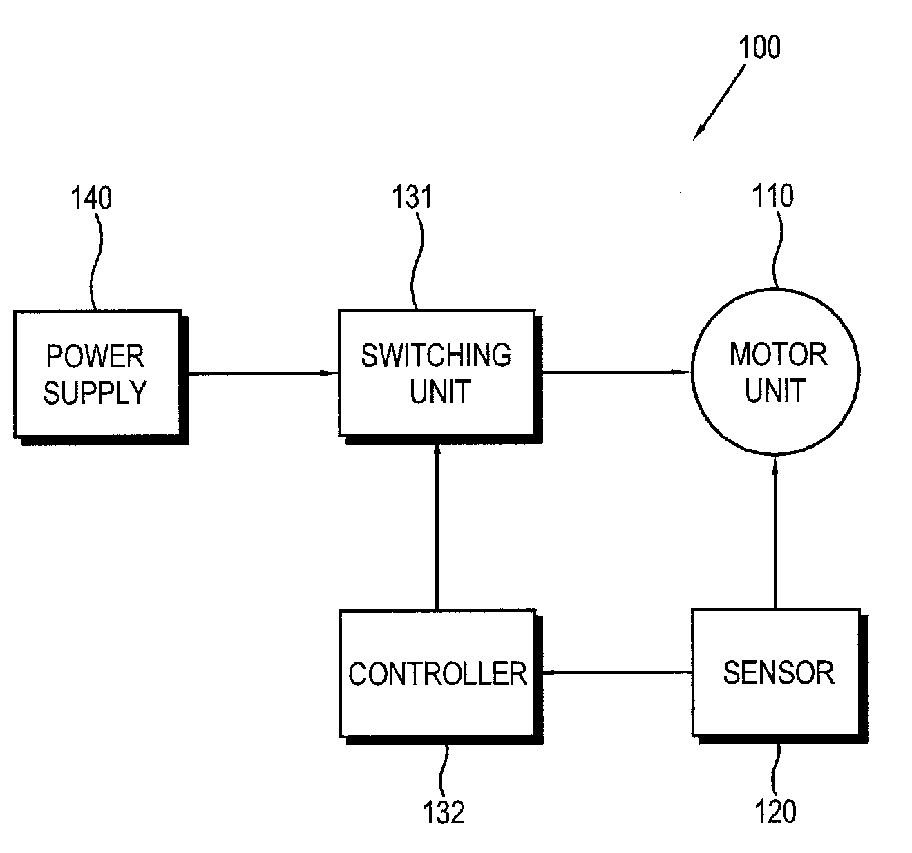
[0031]Hereinafter, exemplary embodiments of the present invention will be described in more detail with reference to accompanying drawings. FIG. 1 is a block diagram of a brushless direct current (BLDC) motor apparatus 100 according to an exemplary embodiment of the present invention.

[0032]The BLDC motor apparatus 100 includes a motor unit 110, a power supply 140, a switching unit 141, a sensor 120, and a controller 132. The motor unit 110, which may be realized as a BLDC motor or the like, rotates to generate a torque under control of the controller 132.

[0033]The power supply 140 supplies driving power, i.e., DC power to the motor unit 110.

[0034]The switching unit 131 is turned on or off according to the control of the controller 132 and performs a switching operation to supply or not to supply the driving power to the motor unit 110.

[0035]The sensor 120 senses a rotated state of the motor unit 110 and sends sensed information to the controller 132.

[0036]The controller 132 controls...


PUM


Abstract

A blushless direct current (BLDG) motor apparatus includes: a stator which is provided with a plurality of windings corresponding to N phases and wound in parallel independently of each other; a rotor which has a plurality of poles corresponding to the plurality of windings and rotates with respect to the stator by excitation of the windings; a switching unit which is provided in the form of a full H-bridge with respect to each phase, comprises a pair of upper switching devices corresponding to a (+) side of the winding and a pair of lower switching devices corresponding to a (−) side of the winding, and performs a switching operation to supply or not to supply driving power to the winding; a first sensing device which senses the phase of the rotor with respect to the stator to determine whether to turn on or off the upper switching device; a second sensing device which is provided in the latter part than the first sensing device and senses the phase of the rotor with respect to the stator to determine whether to turn on or off the lower switching device; and a controller which uses a partial square wave to drive the upper switching device and the lower switching device on the basis of the sensed phase of the rotor, and controls the lower switching device to be turned off later than the upper switching device by more than a time to exhaust an electric current staying in the winding.

Description

TECHNICAL FIELD[0001]The present invention relates to a motor apparatus, and more particularly, to a brushless direct current (BLDC) motor apparatus capable of rotating at high speed and having high efficiency.BACKGROUND ART[0002]Since a brushless direct current (BLDC) motor apparatus has no mechanical contact, it has little noise, long lifespan, simple maintenance such as no need of brush replacement or the like, etc. as compared with a motor apparatus having a brush. Accordingly, the BLDC motor apparatus has been widely used as a motor for industrial equipment, home appliances, transport systems, etc.[0003]With regard to such motor apparatus, technology that enables the motor apparatus to rotate at higher speed, have strong start torque, and output constant power has been disclosed in Korean Patent Registration No. 10-0415493.[0004]According to this technology, a low efficiency region, i.e., a region where a counter electromotive force is generated is not used, so that the motor a...

Claims


Application Information

Patent Timeline
Patent Type & Authority Patents(United States)
IPC IPC(8): H02P6/14H02P6/16H02K1/16H02P6/06H02P6/08
CPCH02P6/16H02P29/028H02P29/032H02P7/28H02P7/29
Inventor HA, BYUNG GILPARK, JI SEOK
Owner CREATION & MOTOR IND
Why Eureka
Try Eureka