Tapered conduits for reactors

a technology of tapered conduits and reactors, applied in the direction of hydrocarbon by saturated bond conversion, chemical/physical/physicochemical processes, separation processes, etc., can solve the problems of large volume for the overall piece of equipment, high cost of systems, etc., and achieve low flow velocities, less turbulence, and large cross-sectional area

Active Publication Date: 2019-08-20
UOP LLC
View PDF35 Cites 3 Cited by
  • Summary
  • Abstract
  • Description
  • Claims
  • Application Information

AI Technical Summary

Problems solved by technology

However, the systems is quite expensive since the large diameter screen cannot be installed or removed through a small upper opening in the vessel, as can the scallops type screen.
This results in a significant volume for the overall piece of equipment.

Method used


Image

  • Tapered conduits for reactors
  • Tapered conduits for reactors
  • Tapered conduits for reactors

Examples


specific embodiments

[0039]While the following is described in conjunction with specific embodiments, it will be understood that this description is intended to illustrate and not limit the scope of the preceding description and the appended claims.

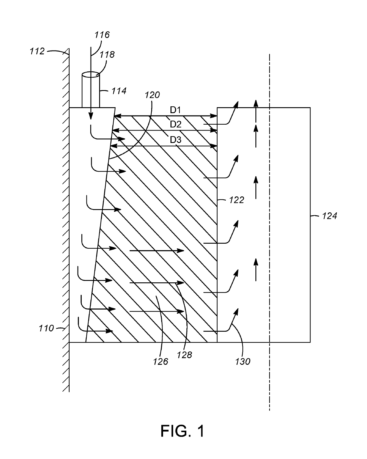
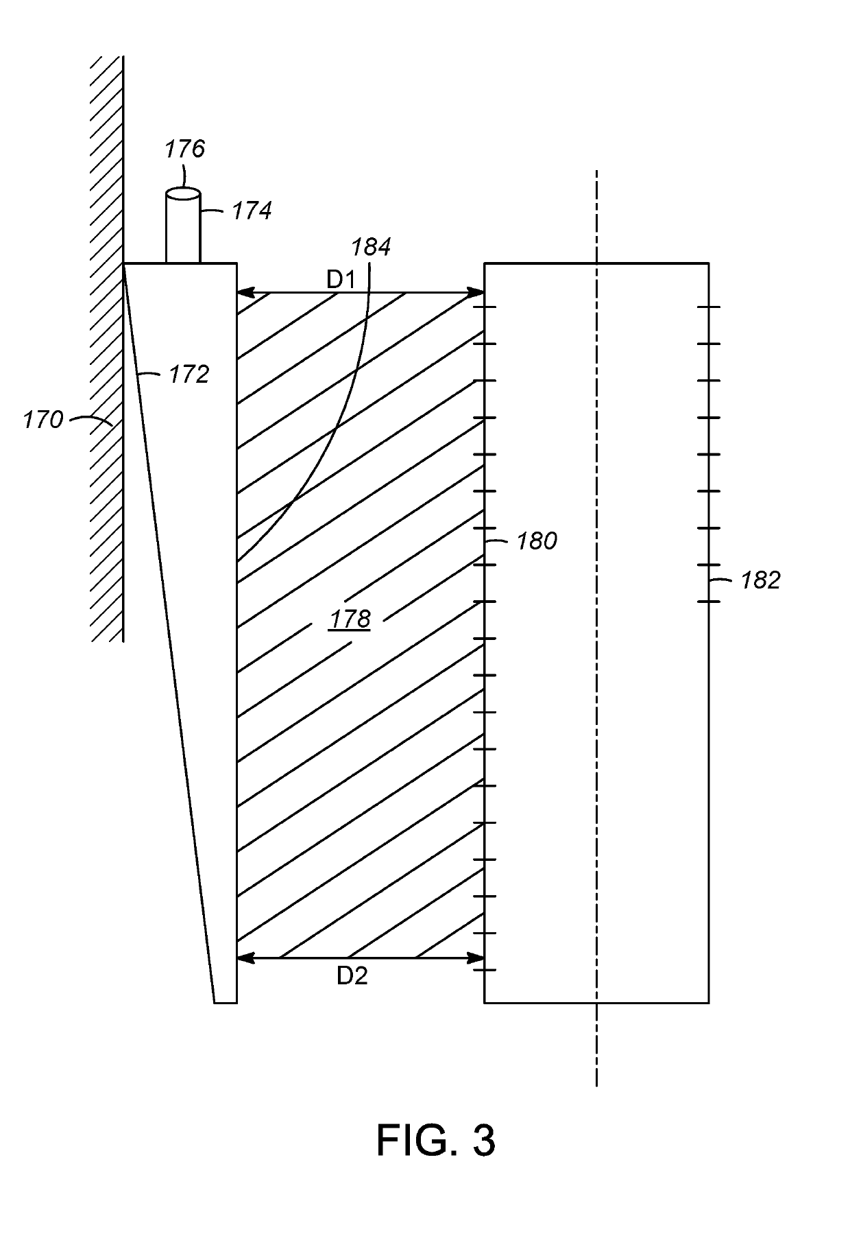
[0040]A first embodiment of the invention is an apparatus directing a fluid in a radial reactor comprising a vertically elongated conduit comprising a front face comprising a surface comprising apertures, two side faces, and a rear face and two ends, wherein a first end of the front face closest to a vapor inlet and a first end of the rear face closest to the vapor inlet are a distance D1 apart and wherein a second end of the front face and a second end of the rear face are a distance D2 apart wherein D1 is greater than D2 and wherein a riser is connected to a top surface of the vertically elongated conduit to allow a gas stream to flow through the riser to the vertically elongated conduit. An embodiment of the invention is one, any or all of prior embodiment...


PUM

PropertyMeasurementUnit
distanceaaaaaaaaaa
distance D1aaaaaaaaaa
distance D2aaaaaaaaaa

Abstract

An apparatus is provided for directing a fluid in a radial reactor comprising: a vertically elongated conduit comprising a front face comprising a surface comprising apertures, two side faces, and a rear face and two ends, wherein an end of the front face and an end of the rear face are a distance D1 apart and wherein a second opposite end of the front face and a second corresponding end of the rear face are a distance D2 apart wherein D1 is greater than D2 and wherein a riser are connected to a top surface of said vertically elongated conduit to allow a gas stream to flow through the riser to the vertically elongated conduit.

Description

CROSS-REFERENCE TO RELATED APPLICATIONS[0001]This application is a Continuation of copending International Application No. PCT / US2016 / 038460 filed Jun. 21, 2016 which application claims benefit of U.S. Provisional Application No. 62 / 184,462 filed Jun. 25, 2015, the contents of which cited applications are hereby incorporated by reference in their entirety.BACKGROUND OF THE INVENTION[0002]This invention relates to the field of fluid particle contact and to an apparatus for contacting fluids and particles. The invention further relates to fluid conduits which form the outer retaining wall for an annular particulate bed used in a radial flow system mounted in a cylindrical vessel. In such systems a fluid typically is directed radially inwardly or outwardly into or out of the particulate bed through openings in the inner surfaces of a plurality of outer, vertically arranged conduit members or through openings in a cylindrical screen basket member which has a smaller diameter than the in...

Claims


Application Information

Patent Timeline
Patent Type & Authority Patents(United States)
IPC IPC(8): B01J8/02B01D53/04B01D53/88
CPCB01J8/0214B01D53/0431B01J8/0278B01D53/885B01J2208/00929B01J2208/0092B01J2208/00849B01J2208/00884B01D2253/102B01J8/065B01J19/2415C07C6/08
Inventor GROTT, JEFFREY R.VETTER, MICHAEL J.
Owner UOP LLC
Why Eureka
Try Eureka