Optical imaging lens
a technology of optical imaging and optical lens, applied in the field of optical devices, can solve the problems of inability to manufacture optical lenses with both a miniaturized size and desirable imaging quality, and still fall behind the imaging quality of optical lens assemblies for vehicles, and achieve the effect of desirable optical performan
- Summary
- Abstract
- Description
- Claims
- Application Information
AI Technical Summary
Benefits of technology
Problems solved by technology
Method used
Image
Examples
first embodiment
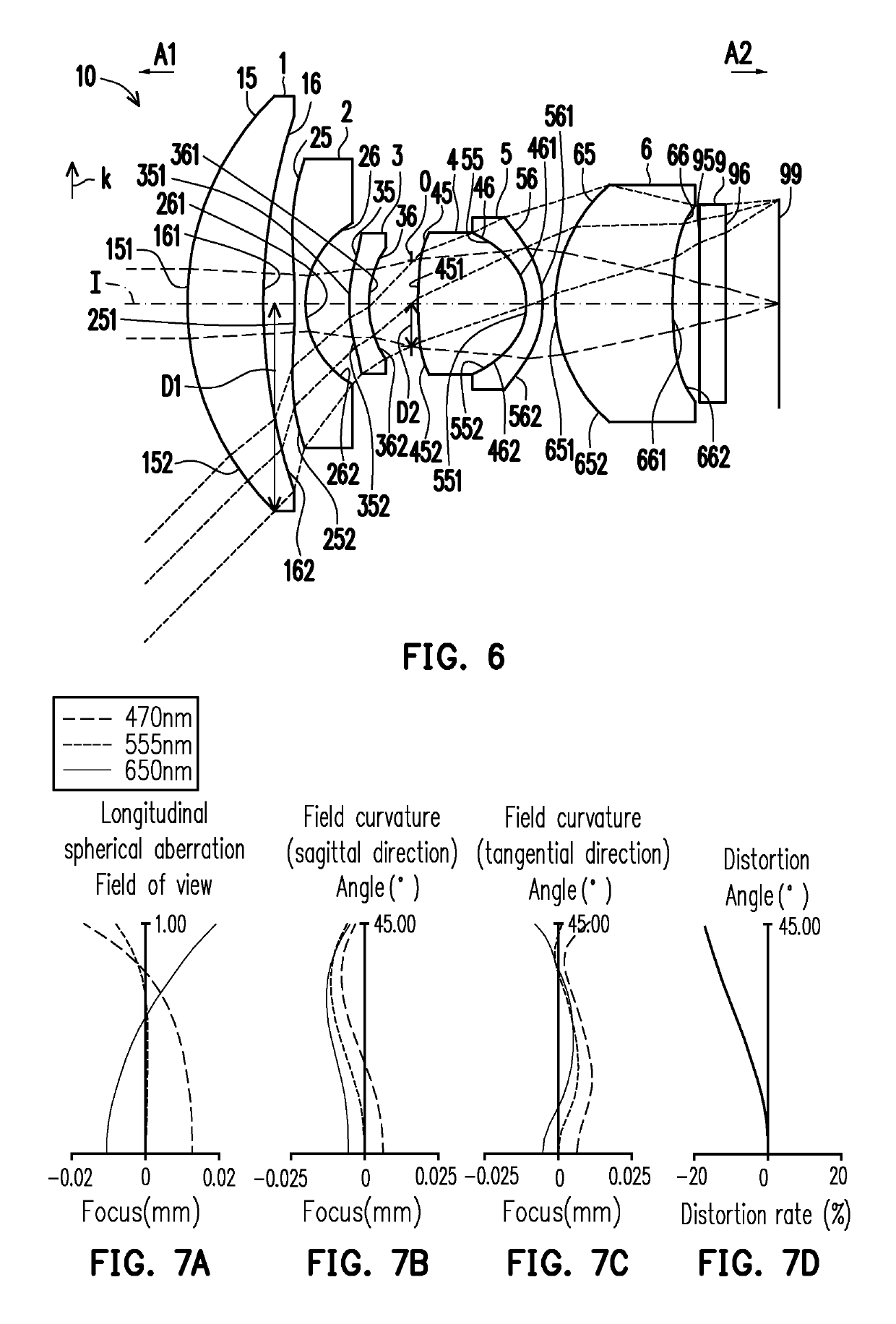
[0079]In the first embodiment, the aperture stop 0 is disposed between the third lens element 3 and the fourth lens element 4. The aperture stop 0 has a radius D2. The radius D2 of the aperture stop 0 refers to a distance between an optical boundary (i.e., a point where a radially outermost marginal ray passing through the aperture stop 0 intersects the aperture stop 0) of the aperture stop 0 and the optical axis I of the optical imaging lens 10 in a radial direction k. In addition, the radial direction k is perpendicular to the optical axis I.
[0080]The fourth lens element 4 has positive refracting power. An optical axis region 451 of the object side surface 45 of the fourth lens element 4 is convex, and a periphery region 452 of the object side surface 45 of the fourth lens element 4 is convex. An optical axis region 461 of the image side surface 46 of the fourth lens element 4 is convex, and a periphery region 462 of the image side surface 46 of the fourth lens element 4 is convex...
second embodiment
[0145]Respective aspheric coefficients of the object side surface 25 of the second lens element 2 to the image side surface 66 of the sixth lens element 6 of the second embodiment in Equation (1) are as shown in FIG. 13.
[0146]In addition, relations of important parameters in the optical imaging lens 10 according to the second embodiment are as shown in FIGS. 46 and 47.
[0147]The longitudinal spherical aberration of the second embodiment is shown in FIG. 11A, and imaging point deviations of the off-axis rays in different heights are controlled within a range of ±0.025 mm. In FIGS. 11B and 11C illustrating the astigmatic field curves, focal distance variations of the three representing wavelengths in the whole field range fall within ±0.025 mm. The distortion aberration shown in FIG. 11D indicates that the distortion aberration of the second embodiment is maintained within a range of ±10%.
[0148]Based on the above, the Fno of the second embodiment is less than the Fno of the first embod...
third embodiment
[0151]Respective aspheric coefficients of the object side surface 25 of the second lens element 2 to the image side surface 66 of the sixth lens element 6 of the third embodiment in Equation (1) are as shown in FIG. 17.
[0152]In addition, relations of important parameters in the optical imaging lens 10 according to the third embodiment are as shown in FIGS. 46 and 47.
[0153]The longitudinal spherical aberration of the third embodiment is shown in FIG. 15A, and imaging point deviations of the off-axis rays in different heights are controlled within a range of ±0.025 mm. In FIGS. 15B and 15C illustrating the astigmatic field curves, focal distance variations of the three representing wavelengths in the whole field range fall within ±0.050 mm. The distortion aberration shown in FIG. 15D indicates that the distortion aberration of the third embodiment is maintained within a range of ±8%.
[0154]Based on the above, the distortion aberration of the third embodiment is less than the distortion...
PUM
 Abstract
Description
Claims
Application Information
 - R&D
- Intellectual Property
- Life Sciences
- Materials
- Tech Scout
- Unparalleled Data Quality
- Higher Quality Content
- 60% Fewer Hallucinations
Browse by: Latest US Patents, China's latest patents, Technical Efficacy Thesaurus, Application Domain, Technology Topic, Popular Technical Reports.
© 2025 PatSnap. All rights reserved.Legal|Privacy policy|Modern Slavery Act Transparency Statement|Sitemap|About US| Contact US: help@patsnap.com


