Optical system for endoscope and endoscope

an endoscope and optical system technology, applied in the field of optical systems for endoscopes, can solve the problems of curvature of field remains, degradation of imaging performance, degrade performance, etc., and achieve the effect of desirable optical performan

Active Publication Date: 2017-02-21
CANON KK
View PDF15 Cites 0 Cited by
  • Summary
  • Abstract
  • Description
  • Claims
  • Application Information

AI Technical Summary

Benefits of technology

[0008]The present invention provides an optical system for an endoscope with which desirable optical performance can be obtained even when the number of relay sets of the relay lens is increased.

Problems solved by technology

However, with the Hopkins type relay lens, curvature of field remains.
This may degrade performance.
However, PTL 1 discloses only the appearance of the triplet and does not disclose a numerical embodiment or aberration.
This may lead to degradation of imaging performance.
This may lead to an increase in the manufacturing cost.
Thus, a further increase in the number of the relay sets of the related-art relay lens used in other relay sets is difficult.

Method used


Image

  • Optical system for endoscope and endoscope
  • Optical system for endoscope and endoscope
  • Optical system for endoscope and endoscope

Examples


first embodiment

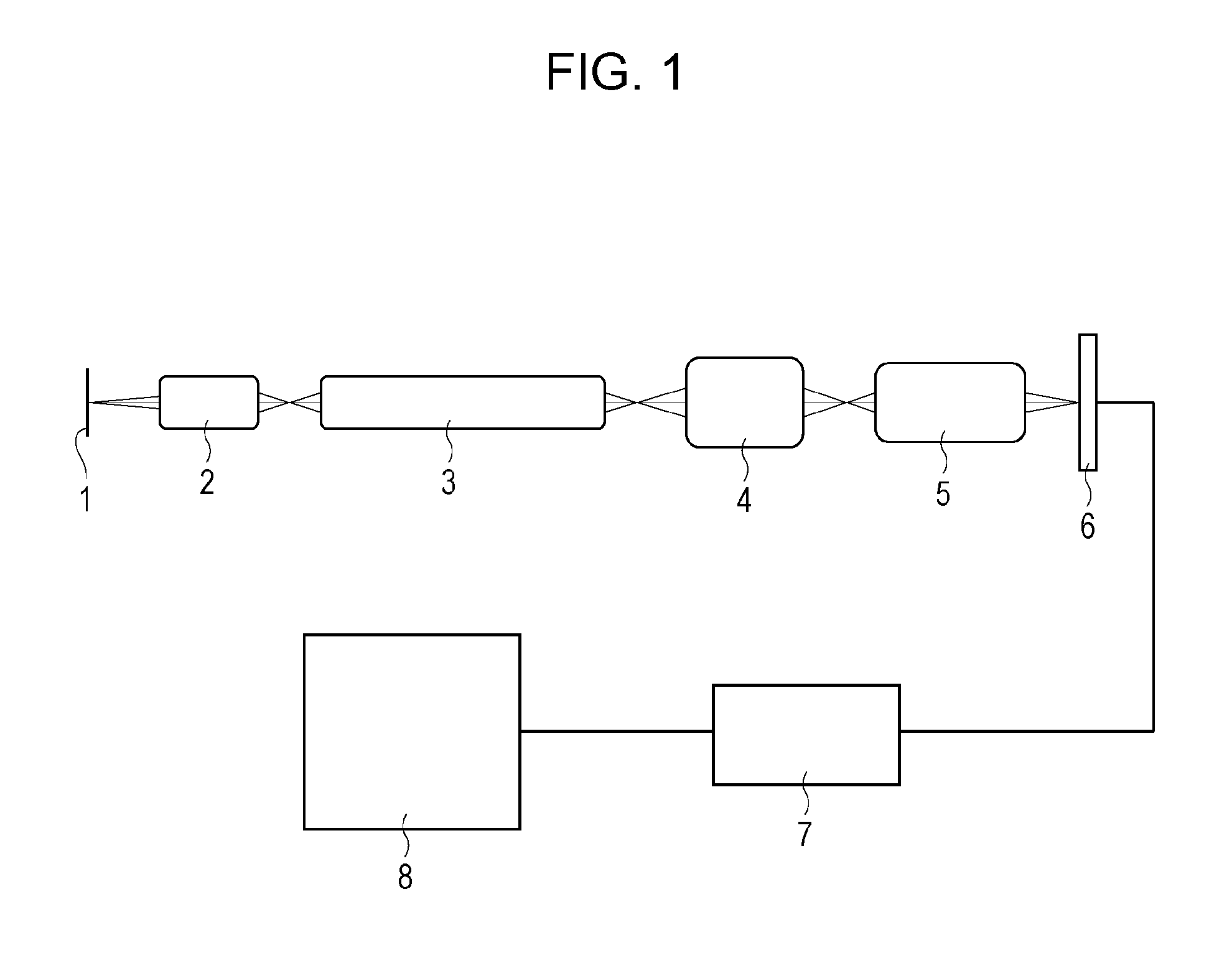
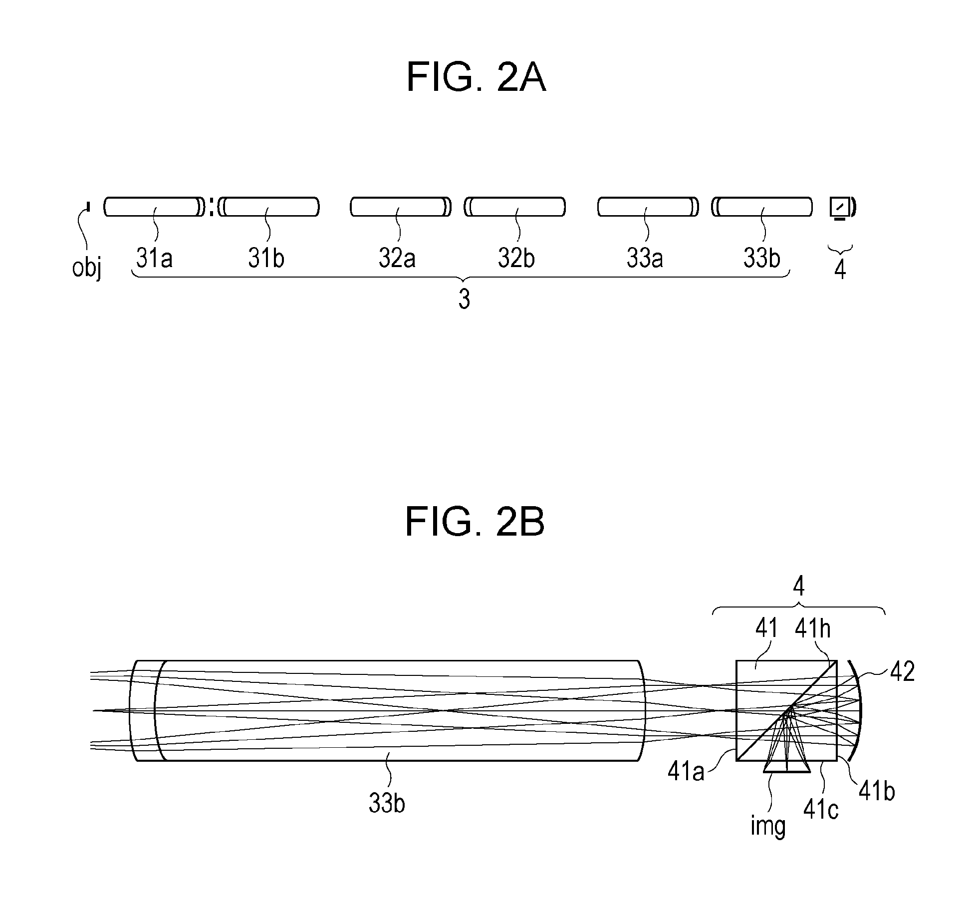
[0039]A first embodiment is described with reference to FIGS. 1 to 6. FIG. 1 is a schematic view of a main portion of an optical system for an endoscope according the present embodiment. Referring to FIG. 1, reference numeral 1 denotes an object, reference numeral 2 denotes an objective lens, reference numeral 3 denotes a relay lens, reference numeral 4 denotes a correction optical system, reference numeral 5 denotes an imaging lens, and reference numeral 6 denotes an image pickup device. In FIG. 1, the object 1 is illuminated with a lighting optical system (not shown), and an image of the object 1 is formed by the objective lens 2 disposed near the object 1. The formed image is optically transmitted through the relay lens 3 and passes through the correction optical system 4. After that, the image of the object 1 is formed again on the image pickup device 6 by the imaging lens 5. The image of the object 1 picked up by the image pickup device 6 is displayed in a display device (not s...

second embodiment

[0047]A second embodiment is described with reference to FIGS. 7 to 9. Portions other than the correction optical system are similar to those of the first embodiment.

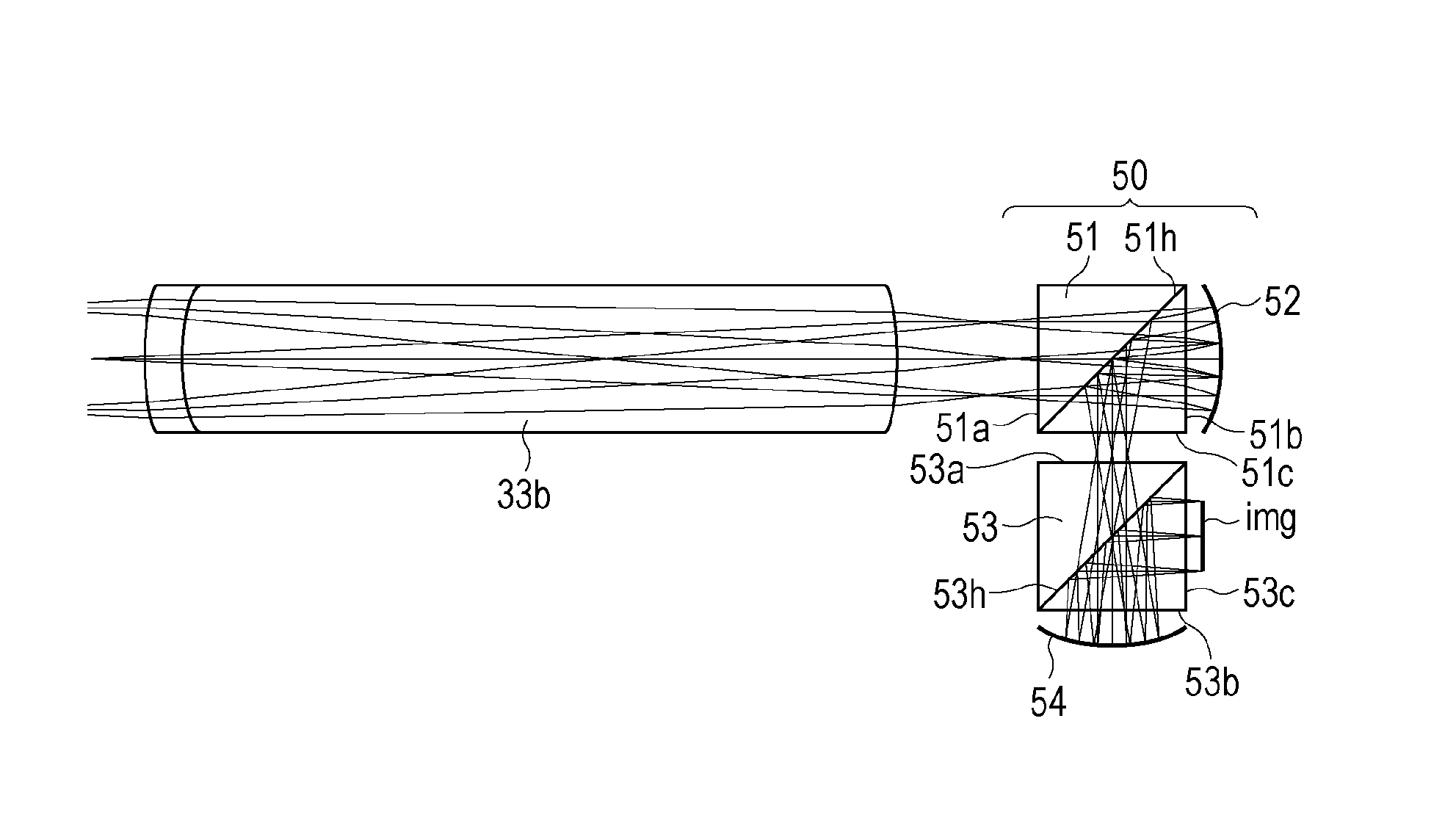
[0048]FIGS. 7A and 7B are sectional views of the relay lens 3 and a correction optical system 50. Specifically, FIG. 7A is a sectional view illustrating an outline of the relay lens 3 and the correction optical system 50, and FIG. 7B is an enlarged sectional view illustrating the correction optical system 50, a region around the correction optical system 50, and optical paths. The relay lens 3 is similar to that used in the first embodiment. Referring to FIG. 7A, a surface denoted as “obj” on the distal end side of the relay lens 3 is an object plane of the relay lens 3 and an image plane of the objective lens 2. The correction optical system 50 is disposed on the proximal end side (right side in FIGS. 7A and 7B) of the relay lens 3. Referring to FIG. 7B, the correction optical system 50 includes a beam splitter 51 as a...

third embodiment

[0056]A third embodiment is described with reference to FIGS. 10 to 12. Portions other than the correction optical system are similar to those of the first embodiment.

[0057]FIG. 10 is an enlarged sectional view illustrating a correction optical system 60, a region around the correction optical system 60, and optical paths. Referring to FIG. 10, the correction optical system 60 includes a beam splitter 61, an aspherical lens 62, and a concave mirror 63. Light beams pass through the rod lenses of the relay lens from lens to lens in order and converge after passing through the rod lens 33b. After that, the light beams enter the beam splitter 61 from a surface 61a, pass through a surface 61h, and exit the beam splitter 61 from a surface 61b. Then, the light beams pass through the aspherical lens 62 and are incident upon the concave mirror 63. The light beams are reflected by the concave mirror 63, pass through the aspherical lens 62 again, enter the beam splitter 61 from the surface 61b...


PUM


Abstract

An optical system for an endoscope includes an objective lens, a relay lens arrangement, and a correction optical system disposed in an optical path on a proximal end side of the objective lens. The correction optical system corrects curvature of field caused by the relay lens arrangement. In the optical system for an endoscope, the correction optical system includes at least one concave mirror having an aspherical surface.

Description

TECHNICAL FIELD[0001]The present invention relates to an optical system for an endoscope, and in particular, the optical system using a relay lens.BACKGROUND ART[0002]A rigid endoscope that uses a relay lens includes an objective lens and a relay lens. The relay lens transmits an image formed by the objective lens toward the proximal end side of the objective lens. By watching light beams that exit from the relay lens through an eyepiece, an object can be directly observed by a human eye. Alternatively, light beams that exit from the relay lens are formed again on an image pickup device by an imaging lens, thereby the obtained image is displayed in a display device for observation.[0003]A relay lens proposed by Hopkins, in which rod lenses are used, is widely used. This Hopkins type relay lens has advantages in that a bright image is obtained, chromatic aberration is corrected, and asymmetric aberration is also corrected. However, with the Hopkins type relay lens, curvature of field...

Claims


Application Information

Patent Timeline
Patent Type & Authority Patents(United States)
IPC IPC(8): G02B21/00G02B23/24G02B17/08G02B27/00G02B27/10
CPCG02B23/243G02B17/08G02B17/0852G02B27/0025G02B27/1066
Inventor SUZUKI, MASAYUKI
Owner CANON KK
Why Eureka
Try Eureka