
Lens barrel

a barrel and lens technology, applied in the field of lenses, can solve the problem of unnecessary provision of such a complicated cam mechanism, and achieve the effect of reducing its siz

Inactive Publication Date: 2005-06-07
FUJI PHOTO OPTICAL CO LTD
View PDF19 Cites 1 Cited by
  • Summary
  • Abstract
  • Description
  • Claims
  • Application Information

AI Technical Summary

Benefits of technology

[0009]In order to overcome such problems, it is an object of the present invention to provide a lens barrel which is less likely to be influenced by external forces, can reduce its size, and can secure appropriate focus adjustment for the lens system.
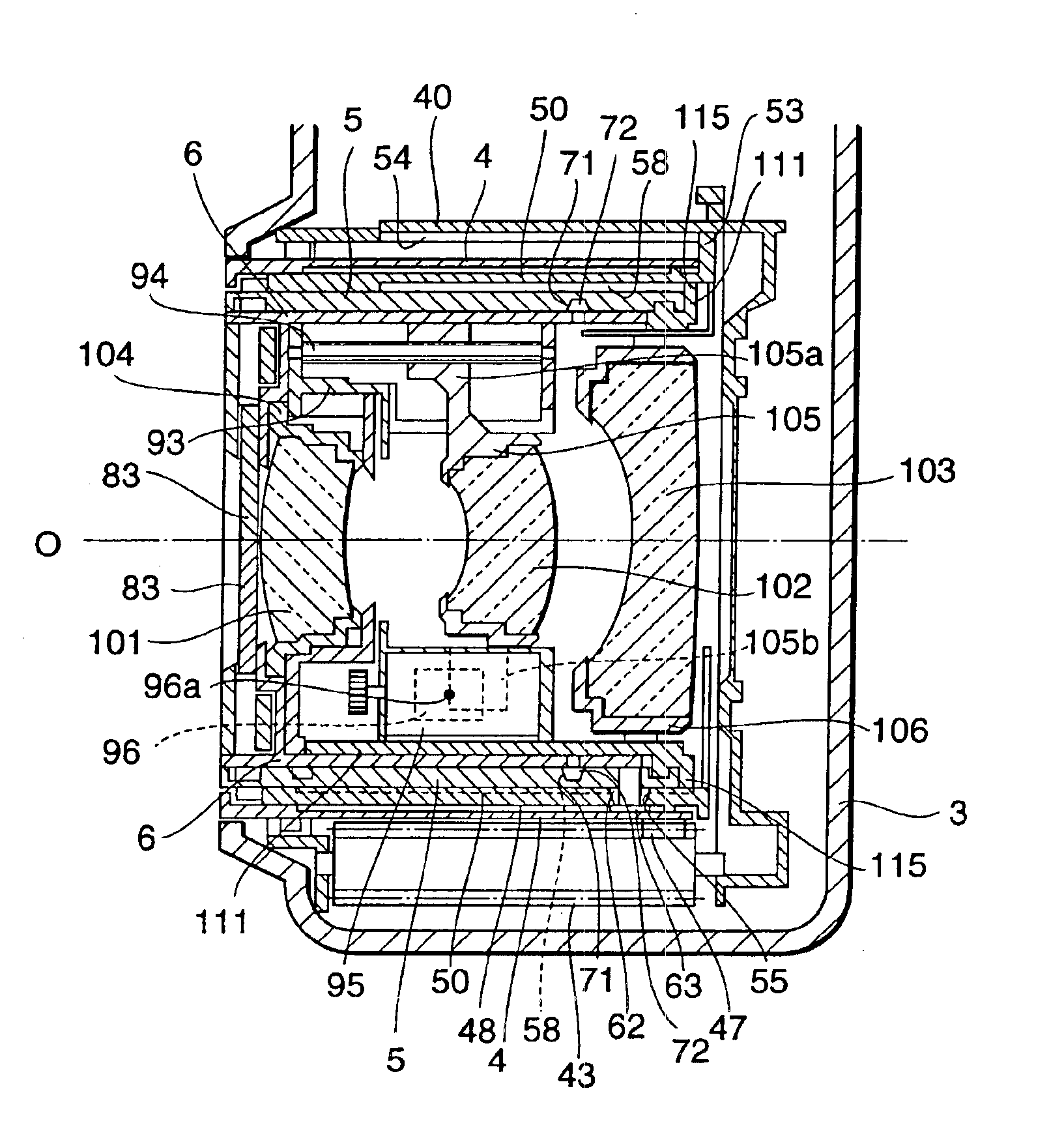
[0011]In the present invention, since all of the individual lens groups are accommodated in a single cylindrical body, it becomes easier to accurately hold the optical axis and posture of each lens group. Also, since the movable lens group is moved by the driving source incorporated in the leading cylindrical body to be expanded, the movable lenses can be moved without deteriorating postures among the lens groups even if an external force is exerted on the lens barrel, whereby desirable optical performances can be secured. Also, zooming is possible by expanding and collapsing the leading cylindrical body, so that delicate cam correction movements between the individual lens groups and the like are unnecessary, whereby accurate zooming can be carried out.
[0012]Also, the lens optical system constituted by the individual lens groups can change its power and adjust its focus by moving the movable lenses by simply expanding or collapsing the leading cylindrical body to which the individual lens groups are attached. Therefore, it is unnecessary to provide a cam link to cylindrical bodies other than the one to which the individual lens groups are attached, so as to drive a specific lens group for changing the power and adjusting the focus, thus making it unnecessary to provide such a complicated cam mechanism. As a consequence, the lens barrel can be made smaller.
[0014]In this configuration, since two fixed lens groups and the movable lens group are accommodated in a single cylindrical body whereas the movable lens group is disposed between the fixed lens groups, the sliding portion and moving mechanism in the movable lens groups can be concealed between the two fixed lens groups. Therefore, dust, dirt, and the like can be kept from attaching to the sliding portion and moving mechanism, whereby delicate driving for focusing can securely be prevented from being obstructed.
[0016]In this configuration, the movable lens group can be controlled so as to precisely move in the optical axis direction upon rotating the threaded shaft. Therefore, precise focusing is possible by moving the movable lens group.

Problems solved by technology

Also, zooming is possible by expanding and collapsing the leading cylindrical body, so that delicate cam correction movements between the individual lens groups and the like are unnecessary, whereby accurate zooming can be carried out.
Therefore, it is unnecessary to provide a cam link to cylindrical bodies other than the one to which the individual lens groups are attached, so as to drive a specific lens group for changing the power and adjusting the focus, thus making it unnecessary to provide such a complicated cam mechanism.

Method used


Image

  • Lens barrel
  • Lens barrel
  • Lens barrel

Examples


Embodiment Construction

[0151]In the following, an embodiment of the present invention will be explained with reference to the accompanying drawings. Among the drawings, constituents identical to each other will be referred to with numerals or letters identical to each other without repeating their overlapping descriptions. Also, ratios of dimensions in the drawings do not always match those explained.

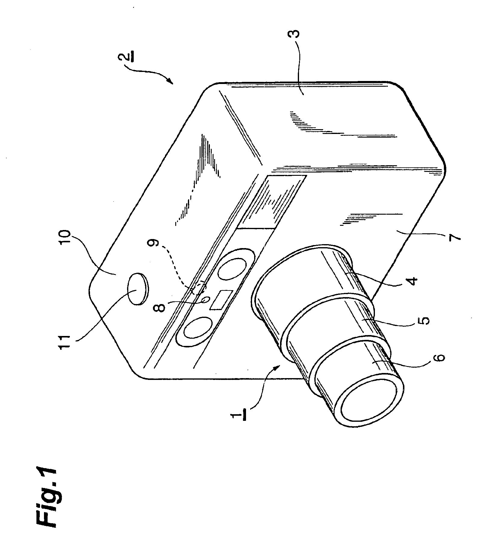
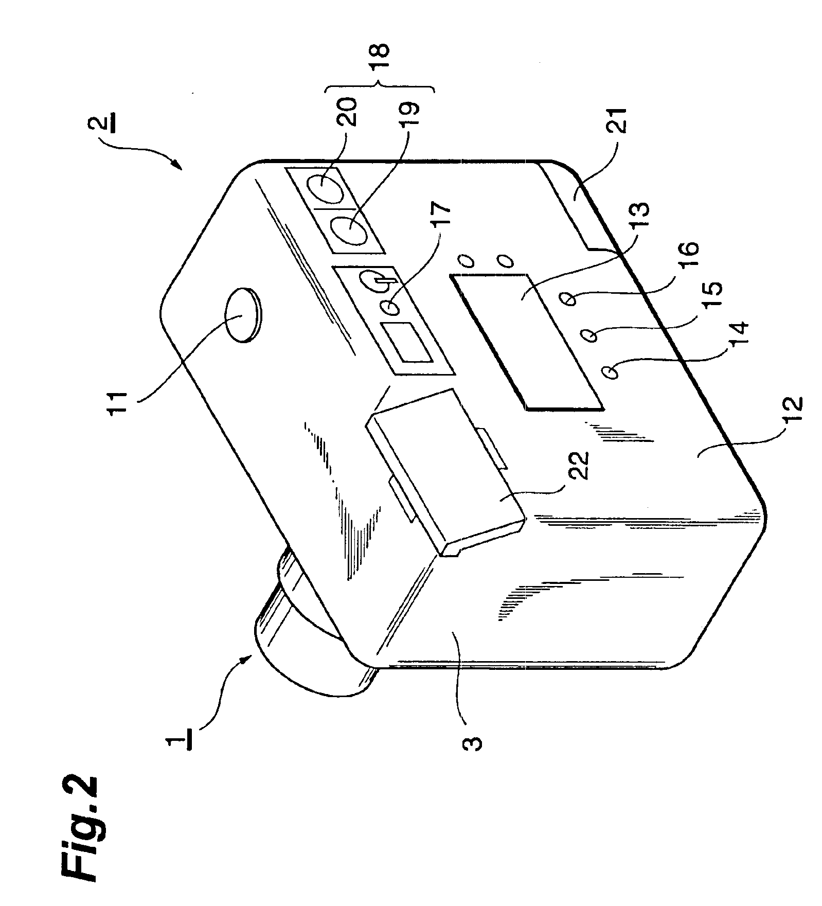
[0152]FIGS. 1 and 2 show a camera using the lens barrel in accordance with this embodiment. As shown in FIG. 1, the lens barrel 1 in accordance with this embodiment is used in a taking optical system of a camera 2. The camera 2 comprises the lens barrel 1 expandable from the front face 7 of a main body 3. The lens barrel 1 has a plurality of cylindrical bodies expandable in a multistage fashion, i.e., a first cylinder 4, a second cylinder 5, and a third cylinder 6. The first cylinder 4 is expandable from and collapsible into the main body 3. The second cylinder 5 is expandable from and collapsible into the fi...


PUM


Abstract

The present invention provides a lens barrel in which all lens groups are attached to a leading cylindrical body. A movable lens group of the lens groups is moved by a driving source incorporated in the leading cylindrical body. The lens barrel is less likely to be influenced by external forces and can be made smaller. The lens barrel includes first, second, and third cylinders, and first, second, and third lens groups attached to the third cylinder, which is extended first among the first, second, and third cylinders. The first and third lens groups are fixed to the third cylinder, and the second lens group is disposed between the first and third lens groups and movable along the optical axis.

Description

BACKGROUND OF THE INVENTION[0001]1. Field of the Invention[0002]The present invention relates to a lens barrel, used in an optical system for an optical device such as a camera, for changing its power and adjusting its focus.[0003]2. Related Background Art[0004]Conventionally known as a lens barrel, used in an optical system for an optical device such as a camera, for changing its power and adjusting its focus is one comprising front and rear group lenses in which the rear group lens is attached to a movable cylinder expandable from a camera body whereas the front group lens is attached to a front cylinder further expandable from the movable cylinder as disclosed in Japanese Patent Application Laid-Open No. HEI 11-218659. The lens barrel disclosed in this publication aims at adjusting the focus by appropriately moving the rear group lens by using a cam groove formed at the inner periphery of the movable cylinder.[0005]Also known as a lens barrel, used in an optical system for an opt...

Claims


Application Information

Patent Timeline
IPC IPC(8): G02B7/10
CPCG02B7/102
Inventor NOZAWA, MASAYANOZAWA, MIEKOONOZUKA, HARUOIWAI, FUMIOSHIMADA, NOBORU
Owner FUJI PHOTO OPTICAL CO LTD
Learn More