Lens driving device

a driving device and lens technology, applied in the direction of optics, mountings, instruments, etc., can solve the problems of difficult to obtain desirable stable optical characteristics, difficult to arrange the lens between the two guide shafts, and difficult to move the lens frame smoothly along the guide shafts. achieve optimal weight balance, high precision, smooth and stable

Active Publication Date: 2011-07-05
COPAL CO LTD
View PDF24 Cites 2 Cited by
  • Summary
  • Abstract
  • Description
  • Claims
  • Application Information

AI Technical Summary

Benefits of technology

[0026]This structure allows the center of gravity of the apparatus to be positioned between the main guide shaft and the auxiliary guide shaft or nearby, while making the apparatus smaller. Also, the weight balance of the apparatus can be set optimally even though the lens frame is formed like a cantilever.
[0027]The lens drive apparatus having the above

Problems solved by technology

However, there are cases where the lens cannot be arranged between the two guide shafts because of layout limitations and other conditions.
Therefore, when simply formed like a cantileve

Method used


Image

  • Lens driving device
  • Lens driving device
  • Lens driving device

Examples


Embodiment Construction

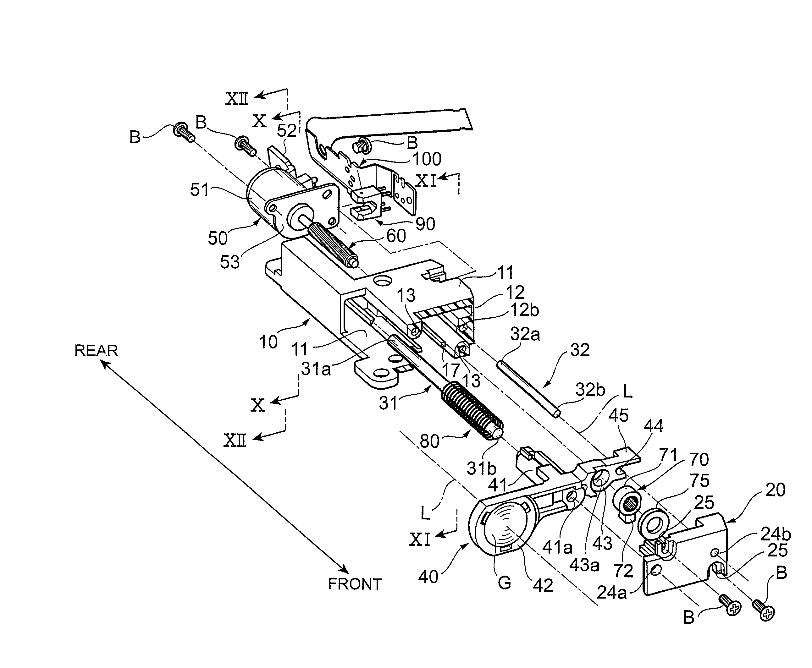
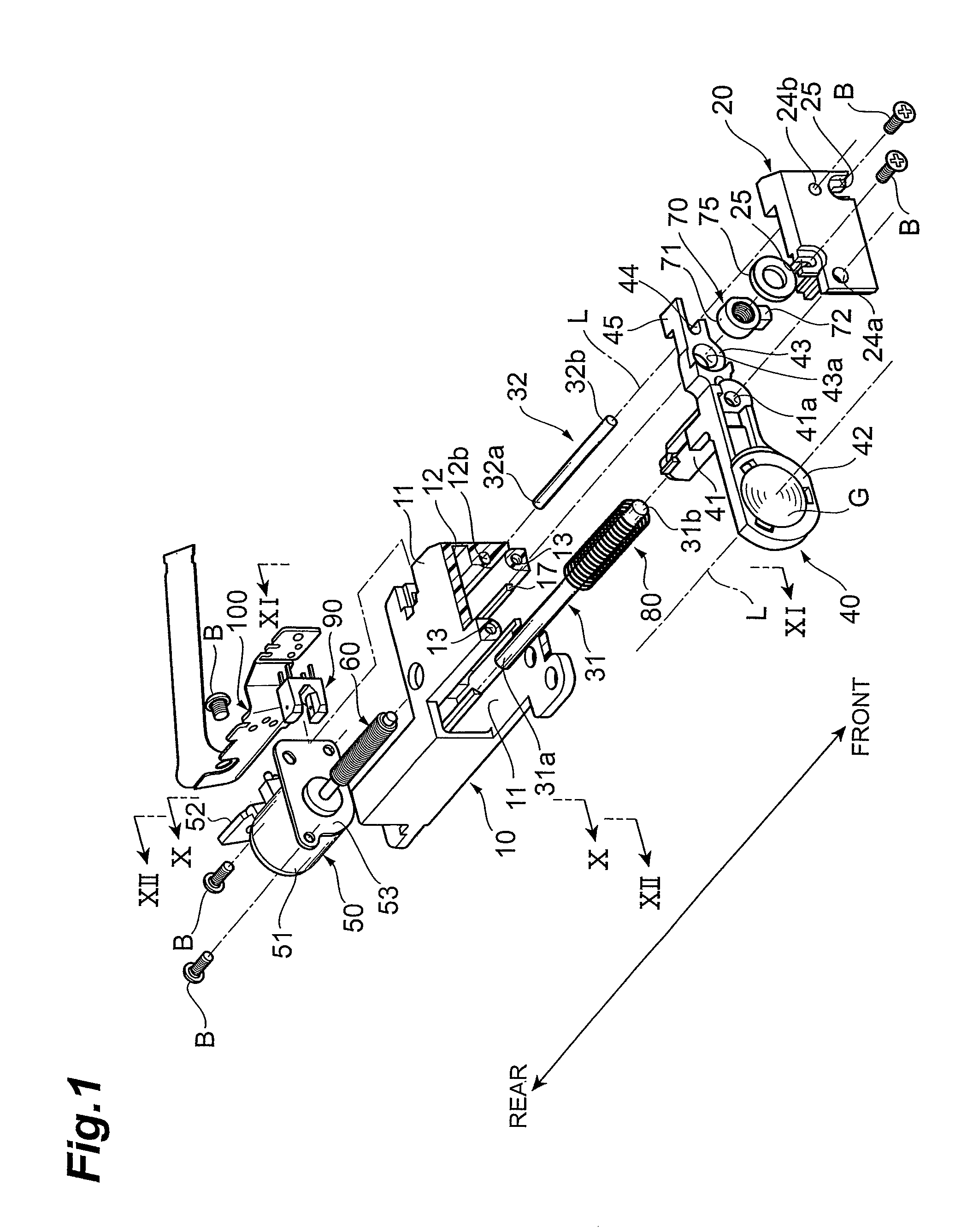
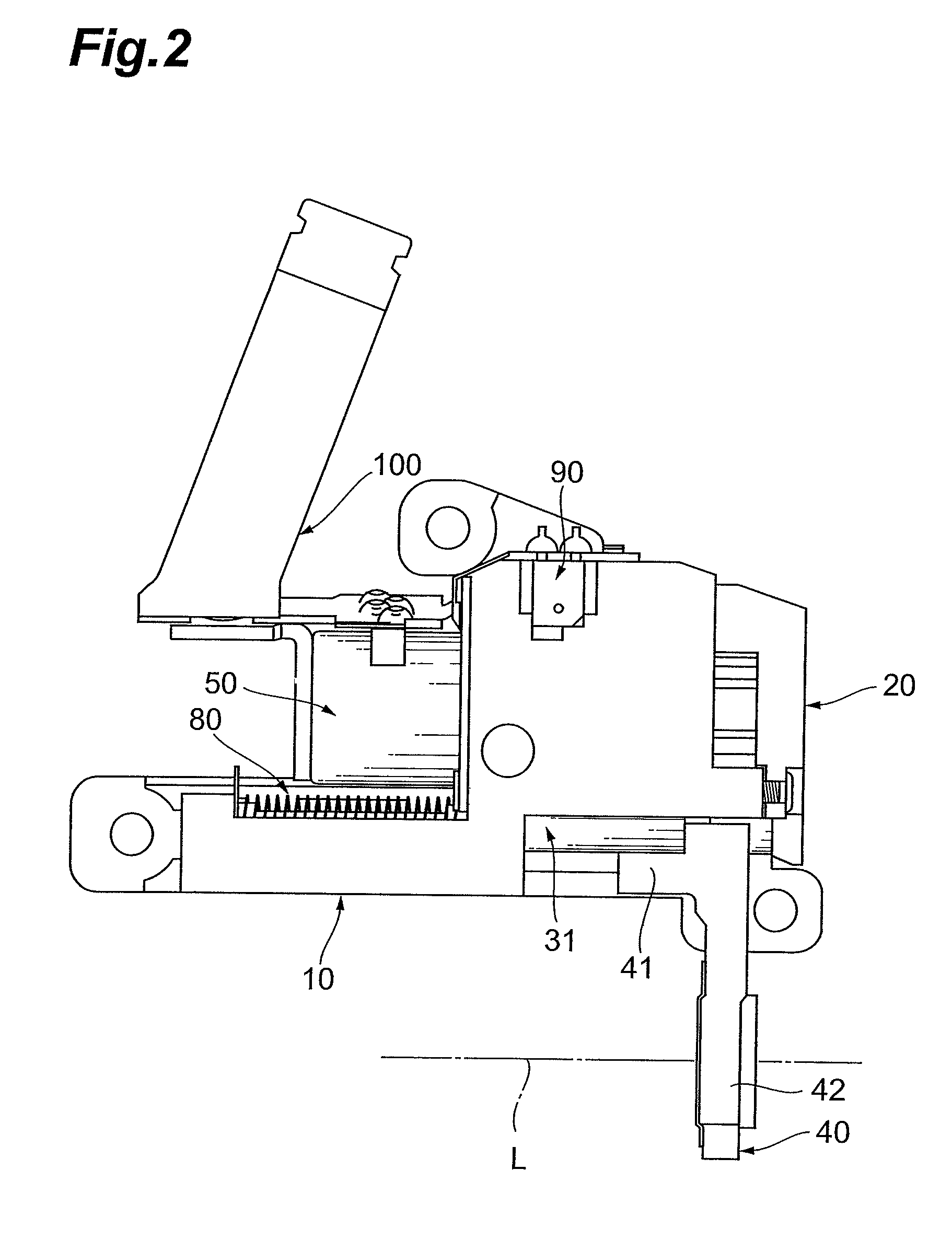
[0040]In the following, the best embodiment of the present invention will be explained with reference to the accompanying drawings. FIGS. 1 to 12 illustrate an embodiment of the lens drive apparatus in accordance with the present invention, in which FIG. 1 is an exploded perspective view of the apparatus, FIG. 2 is a side view of the apparatus, FIG. 3 is a front view of the apparatus, FIGS. 4 and 5 are perspective and end face views of a base constituting a part of the apparatus, FIGS. 6 and 7 are perspective and end face views of a cover constituting a part of the apparatus, FIG. 8 is a front view illustrating an arrangement relationship of the apparatus, FIG. 9 is a side view of a lens frame constituting a part of the apparatus, and FIGS. 10 to 12 are longitudinal sectional views of the apparatus. The cross-sectional directions of FIGS. 10 to 12 are illustrated in FIGS. 1 and 8.

[0041]About Overall Structure and Constituents of Apparatus

[0042]First, the overall structure of the len...


PUM


Abstract

A lens drive apparatus includes a base, a lens frame, a nut movable with the lens frame while being threadably engaged with a lead screw, a main guide shaft for guiding the lens frame along an optical axis, an auxiliary guide shaft for guiding the lens frame along the optical axis while inhibiting the lens frame from rotating, and a cover, arranged so as to oppose the base for mating with and securing the main guide shaft and auxiliary guide shaft. The lens frame has a lens holding part projecting out of the base and cover. The base and cover have a first positioning pin and a first positioning hole, which are provided near the main guide shaft, and a second positioning pin and a second positioning hole, which are provided at a position distanced from the main guide shaft. The foregoing can yield a lens drive apparatus having high optical performances, which can be assembled with a high precision.

Description

BACKGROUND OF THE INVENTION[0001]I. Technical Field[0002]The present invention relates to a lens drive apparatus which employs a threaded engagement structure composed of a lead screw and a nut to drive a lens frame holding a lens along an optical axis.[0003]II. Description of the Related Art[0004]A conventional lens drive apparatus comprises a base, a lens frame holding a lens, two guide shafts which are secured to the base on both sides holding the lens so as to guide the lens frame along an optical axis, a motor secured to the base, a lead screw which is directly connected to the motor and driven thereby to rotate, a nut which is held by the lens frame so as to threadably engage the lead screw, a coil spring for urging the lens frame toward the nut, and the like as described in Japanese Patent Application Laid-Open No. 2004-34139 and Japanese Patent Application Laid-Open No. 2006-114117, for example. In such an apparatus, the motor rotates the lead screw, so as to screw-feed the ...

Claims


Application Information

Patent Timeline
IPC IPC(8): G02B7/02
CPCG02B7/08G02B7/102
Inventor ISHIMASA, TORUUCHIKAWA, SATOKO
Owner COPAL CO LTD
Why Eureka
Try Eureka