Saddle ride, fuel cell powered vehicle

a fuel cell and ride technology, applied in the direction of electric propulsion mounting, battery/fuel cell control arrangement, cycles, etc., can solve the problems of difficult to apply the technique of contriving a reduction in the difficulty of swinging the pivot shaft to swingably support the swing arm, so as to reduce the overall vehicle body length, shorten the wheel base, and enhance draining performance

Inactive Publication Date: 2008-10-02
HONDA MOTOR CO LTD
View PDF5 Cites 12 Cited by
  • Summary
  • Abstract
  • Description
  • Claims
  • Application Information

AI Technical Summary

Benefits of technology

[0026]According to the embodiment of the present invention, the fuel cell is formed in a substantially rectangular parallelepiped shape, and is disposed on the lower side of the seat in the state of being inclined toward the vehicle body rear side from the state of having its longitudinal direction in the vertical direction; and the pivot shaft is disposed in a range which is defined on the front side of a vertex, located at the rear end, of the side-view rectangle of the fuel cell and which is defined on the rear side of a vertex, located at the lower end, of the side-view rectangle of the fuel cell. Therefore, the pivot shaft can be disposed rather on the vehicle body front side, as compared with the case where, for example, the fuel cell is disposed with its longitudinal direction set in the vehicle body front-rear direction. This makes it possible to contrive a reduction in the overall vehicle body length by shortening the wheel base, while securing a sufficient swing arm length. Furthermore, since the fuel cell is inclined toward the vehicle body rear side, the reaction product water produced at the time of power generation and collecting on the lower side of the fuel cell is permitted to flow favorably, whereby draining performance can be enhanced.
[0027]According to the embodiment of the present invention, the pivot shaft is disposed in a range which is defined on the lower side of a vertex, located at the rear end, of the side-view rectangle of the fuel cell and which is defined on the upper side of a vertex, located at the lower end, of the side-view rectangle of the fuel cell. Therefore, the fuel cell is disposed on the vehicle body lower side, whereby a lowering of the center of gravity can be contrived, and a compacter vehicle body can be obtained.
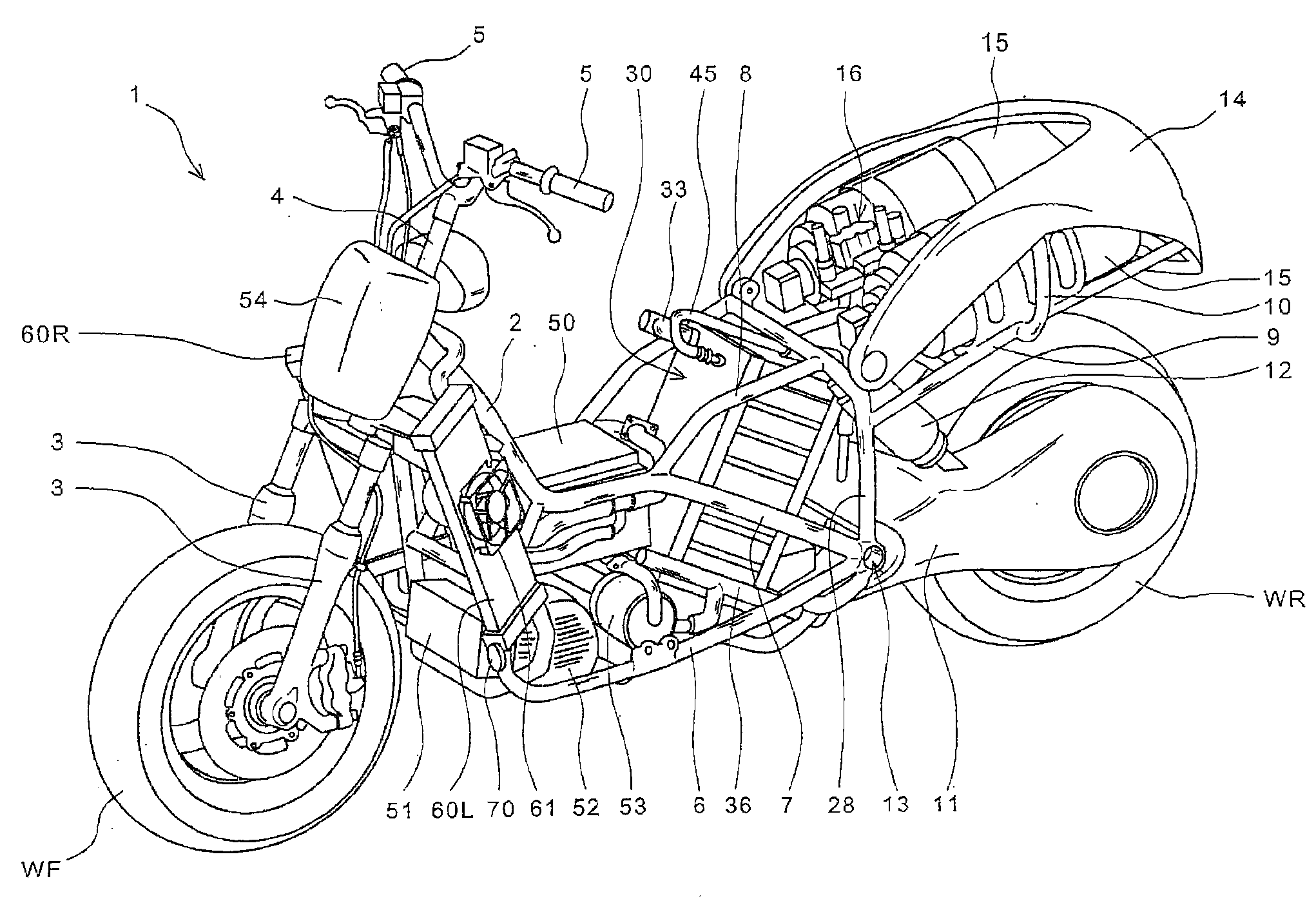
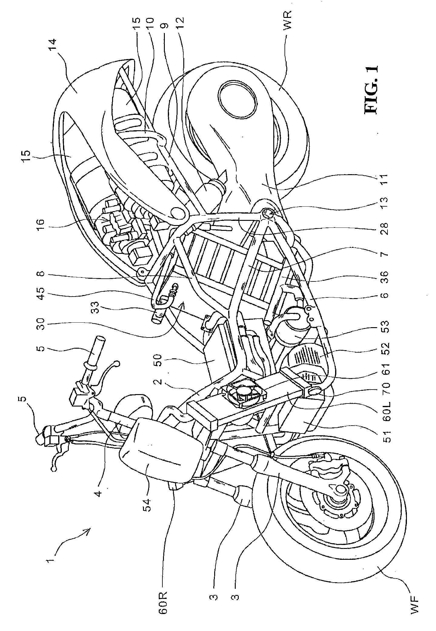
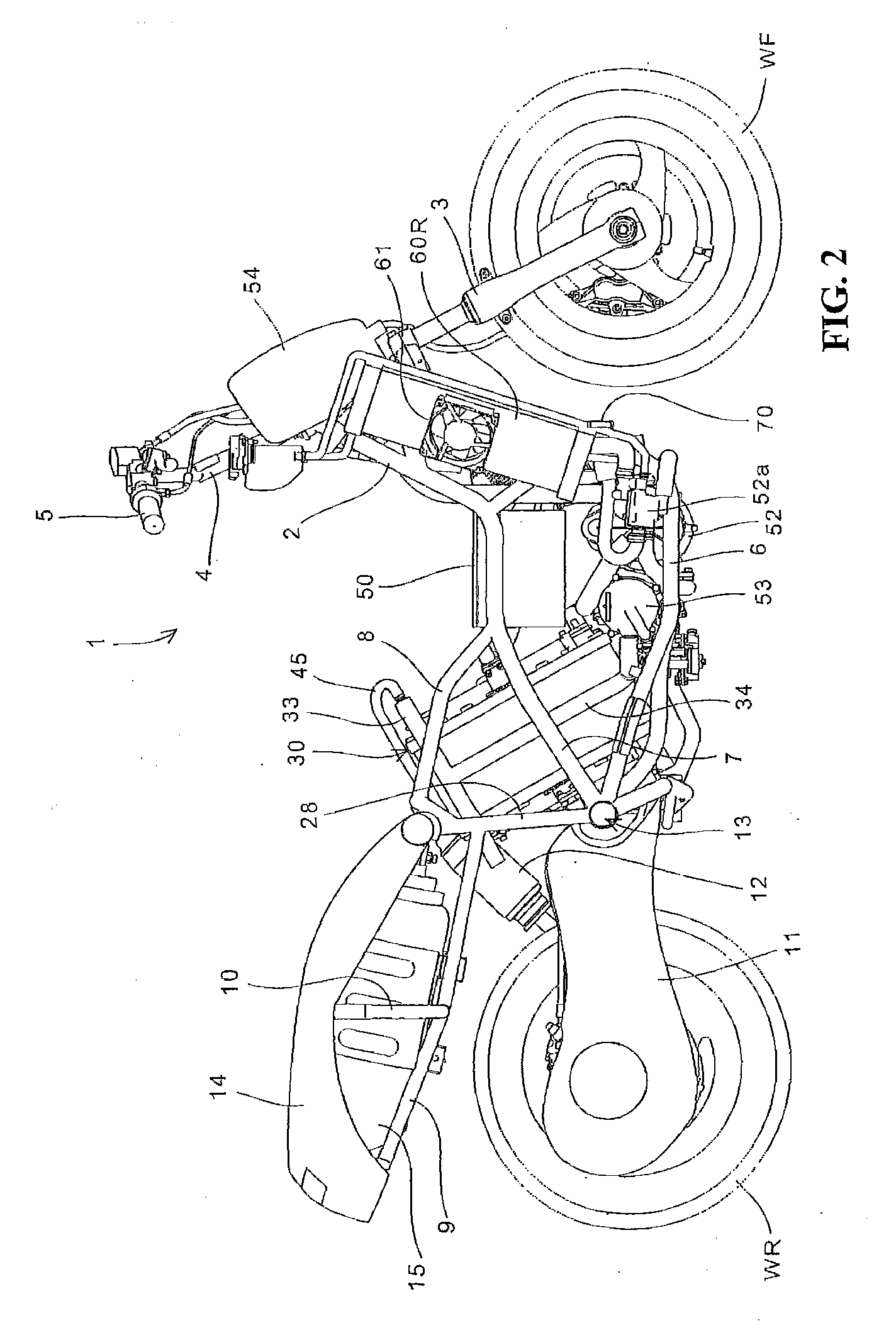
[0028]According to the embodiment of the present invention, the saddle ride, fuel cell powered vehicle further includes a steering handle for steering a front wheel; and foot rest parts for a driver are provided between the steering handle and the seat, and the fuel cell is disposed on the vehicle body rear side of the foot rest parts so that the center of gravity of the fuel cell is located on the vehicle body front side relative to the center in the front-rear direction of a seating part on which to seat the driver at the time of riding. Therefore, the center of gravity of the fuel cell can be set on the vehicle body front side relative to the center of gravity of the driver at the time of riding, the centers of gravities of heavyweight bodies can be concentrated substantially in the center in the vehicle front-rear direction, and the weight balance in the front-rear direction of the vehicle body can be enhanced. In addition, since the fuel cell is disposed on the vehicle body rear side of the foot rest parts, the rider does not stride over the fuel cell when he gets on or gets off the vehicle, so that it is made easier for the rider to get on or get off the saddle ride, fuel cell powered vehicle.
[0029]According to the embodiment of the present invention, the vehicle saddle ride, fuel cell powered vehicle further includes hydrogen reserving means for reserving hydrogen gas to be supplied to the fuel cell; the hydrogen reserving means is disposed on the upper side of a rear wheel; and a hydrogen gas supply port of the fuel cell is provided on the upper part side in the longitudinal direction of the fuel cell. Therefore, the distance between the hydrogen reserving means and the hydrogen gas suction port of the fuel cell is reduced, the hydrogen supply path such as the fuel gas pipe is shortened, and pressure loss can be thereby reduced.
[0030]According to the embodiment of the present invention, the fuel cell includes a case for containing a plurality of cells stacked, a reactant gas suction port for supplying the reactant gas from the upper side of the case, and an unreacted gas discharge port for discharging the unreacted gas from the lower side of the case; and two reactant gas suction ports are provided so as to be substantially perpendicular to the plane of the cells and to be located on opposite sides of the case. Therefore, it becomes easy to increase the quantity of the reactant gas sucked in, and the reactant gas supplying efficiency can be enhanced. As a result, it becomes possible to supply the reactant gas in a sufficient quantity necessary for the fuel cell, without enlarging a supercharger. In addition, since the reactant gas is introduced through both side parts of the case, the reactant gas can be supplied evenly with regard to the stacking direction of the cell stack, as compared for example with a system in which the reactant gas is sucked in from either one of the opposite sides, and it becomes possible to enhance the power generation efficiency of the fuel cell.
[0031]According to the embodiment of the present invention, the fuel cell powered vehicle further includes a suction-side manifold for connecting the two reactant gas suction ports to each other on the outside of the case, a supercharger for forcibly supplying the reactant gas, and a reactant gas pipe for connection between the supercharger and the suction-side manifold. Therefore, by use of the single reactant gas pipe, it becomes possible to supply the reactant gas simultaneously through the two reactant gas suction ports. In addition, since the layout position of the reactant gas pipe can be modified by modifying the position of connection with the suction-side manifold, the layout of the reactant gas pipe is not limited although the two reactant gas suction ports are provided, and it becomes possible to enhance the degree of freedom in designing the vehicle body and the like.

Problems solved by technology

According to the technique disclosed in Japanese Patent Laid-open No. 2005-112094, however, the longitudinal direction of the fuel cell is set in the vehicle body front-rear direction, so that it is difficult for a pivot shaft for swingably supporting a swing arm to be located rather on the front side relative to a rear end part of the fuel cell.
This makes it difficult to apply the technique of contriving a reduction in the overall vehicle body length by shortening the wheel base, while securing a sufficient swing arm length.
However, Japanese Patent Laid-open No. 2003-291849 contains little investigation as to a configuration for a saddle ride, fuel cell powered vehicle such as a motorcycle and a three-wheel vehicle having no compartment, wherein leakage of hydrogen from any part of hydrogen reserving means and each hydrogen passage can be detected.

Method used


Image

  • Saddle ride, fuel cell powered vehicle
  • Saddle ride, fuel cell powered vehicle
  • Saddle ride, fuel cell powered vehicle

Examples


Embodiment Construction

[0051]FIG. 1 is a perspective view of a fuel cell powered vehicle 1 according to an embodiment of the present invention. FIG. 2 is a right side view of the fuel cell powered vehicle 1. The fuel cell powered vehicle 1 as a saddle ride, motorcycle has a fuel cell power generation system including a cell stack (inclusive of electrodes, a separator, an electrolyte membrane and the like) having a plurality of cells stacked, a fuel (hydrogen) gas supply system for supplying hydrogen gas as a fuel to the cell stack, and a reactant gas supply system for supplying an oxygen-containing reactant gas (air) to the cell stack. Hereinafter, a substantially rectangular parallelepiped casing containing the cell stack therein will, as a whole, be referred to as a fuel cell 30.

[0052]The fuel cell powered vehicle 1 has a framework including a main frame 2 to which a head pipe for turnably supporting a handle post 4 of a steering handle 5 is joined, an under frame 6 joined to the head pipe and extending...


PUM


Abstract

A saddle ride vehicle includes a fuel cell formed in a rectangular, parallelepiped shape disposed below a vehicle seat. The fuel cell is inclined toward a vehicle rear. A pivot shaft is disposed in a range X defined forwardly of a vertex P of a side-view rectangle of the fuel cell, and defined rearwardly of a vertex Q of the side-view rectangle, and is disposed in a range Y defined below the vertex P and defined above the vertex Q. Foot rest parts are disposed between a steering handle and the seat. The fuel cell is disposed on the side of the foot rest parts, so that the center of gravity G1 of the fuel cell is located on the vehicle body front side relative to the seating part center G2 in the front-rear direction of the center of gravity of the driver at the time of riding.

Description

CROSS-REFERENCE TO RELATED APPLICATION[0001]The present application claims priority under 35 U.S.C. §119 to Japanese Patent Application Nos. 2007-094250, 2007-094246, and 2007-094248, each of which was filed Mar. 30, 2007, the entire contents of which are hereby incorporated by reference.BACKGROUND OF THE INVENTION[0002]1. Field of the Invention[0003]The present invention relates to a saddle ride, fuel cell powered vehicle, and particularly to a saddle ride, fuel cell powered vehicle in which the overall length of the vehicle can be reduced while keeping an appropriate weight balance in the vehicle body front-rear direction. The fuel cell powered vehicle having such a configuration that the efficiency in supplying a reactant gas to a fuel cell can be enhanced, that a sufficient amount of the reactant gas can be sucked into the fuel cell without enlarging a supercharger, and that leakage of hydrogen from any part of hydrogen reserving means and each hydrogen passage can be detected a...

Claims


Application Information

Patent Timeline
Patent Type & Authority Applications(United States)
IPC IPC(8): B60L11/18B62K11/00
CPCB60L11/1881B60L11/1892B62K11/00B62K11/10B62K2202/00B62K2204/00Y02T90/34B60L58/30B60L58/33Y02T90/40
Inventor HORII, YOSHIYUKIMAKUTA, YOHEIKOITABASHI, KEISUKEITO, MASAMOTO
Owner HONDA MOTOR CO LTD
Why Eureka
Try Eureka