
Fully adjustable lift system

a fully adjustable, lift mechanism technology, applied in the field of agricultural implements, can solve the problems of complex and expensive hydraulic valves, circuitry, controls, and the operation and control of such prior art lift mechanisms are often cumbersome and time-consuming, and require extensive operator training and knowledge. , to achieve the effect of improving the balance of weigh

Active Publication Date: 2016-09-01
BLUE LEAF I P INC
View PDF4 Cites 11 Cited by
  • Summary
  • Abstract
  • Description
  • Claims
  • Application Information

AI Technical Summary

Benefits of technology

The present invention has the advantage of being simple and reliable, providing strong and stable operation. It is also easy to control and adjust, making it ideal for use in agricultural or industrial implements. The lift and gauge wheel lift mechanism also improves weight balance by locating the cylinder used to raise and lower the wheels between the middle and the front of the frame.

Problems solved by technology

This requires complicated and expensive hydraulic valves, circuitry, and controls.
Further, operation and control of such prior art lift mechanisms is often cumbersome and time consuming, requiring extensive operator training and knowledge.
Alternately, prior art lift mechanisms minimize the number of cylinders involved, but at the expense of front to back and side to side levelling control and adjustability.

Method used


Image

  • Fully adjustable lift system
  • Fully adjustable lift system
  • Fully adjustable lift system

Examples


Embodiment Construction

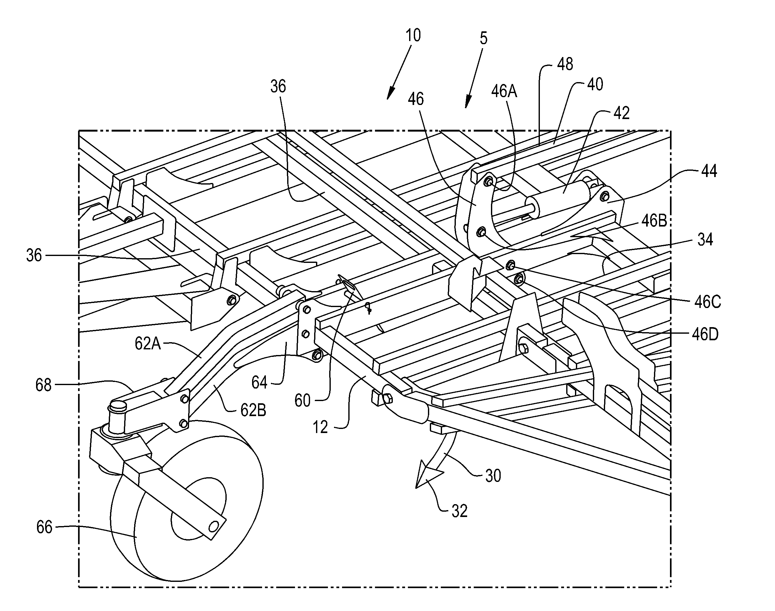
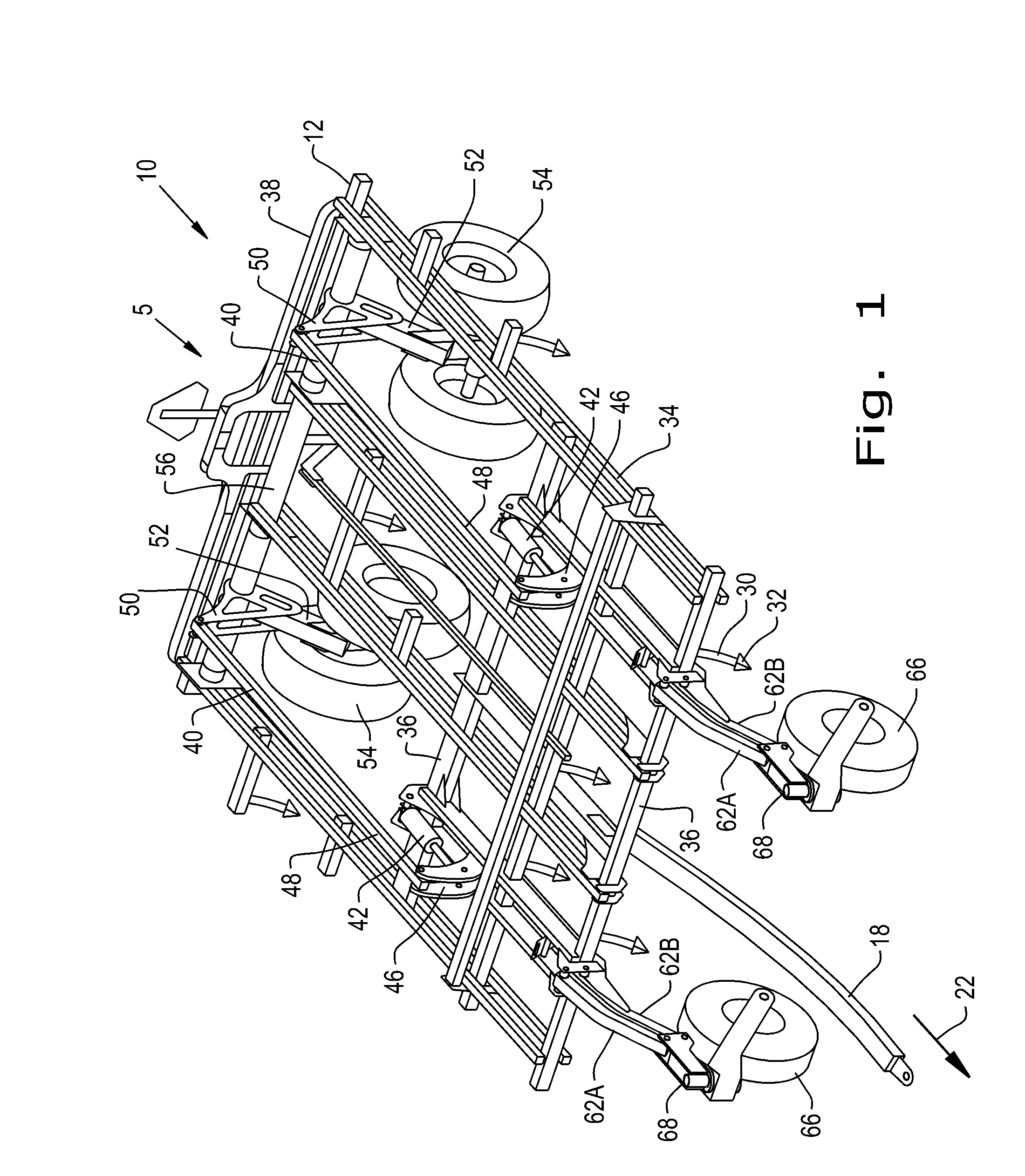
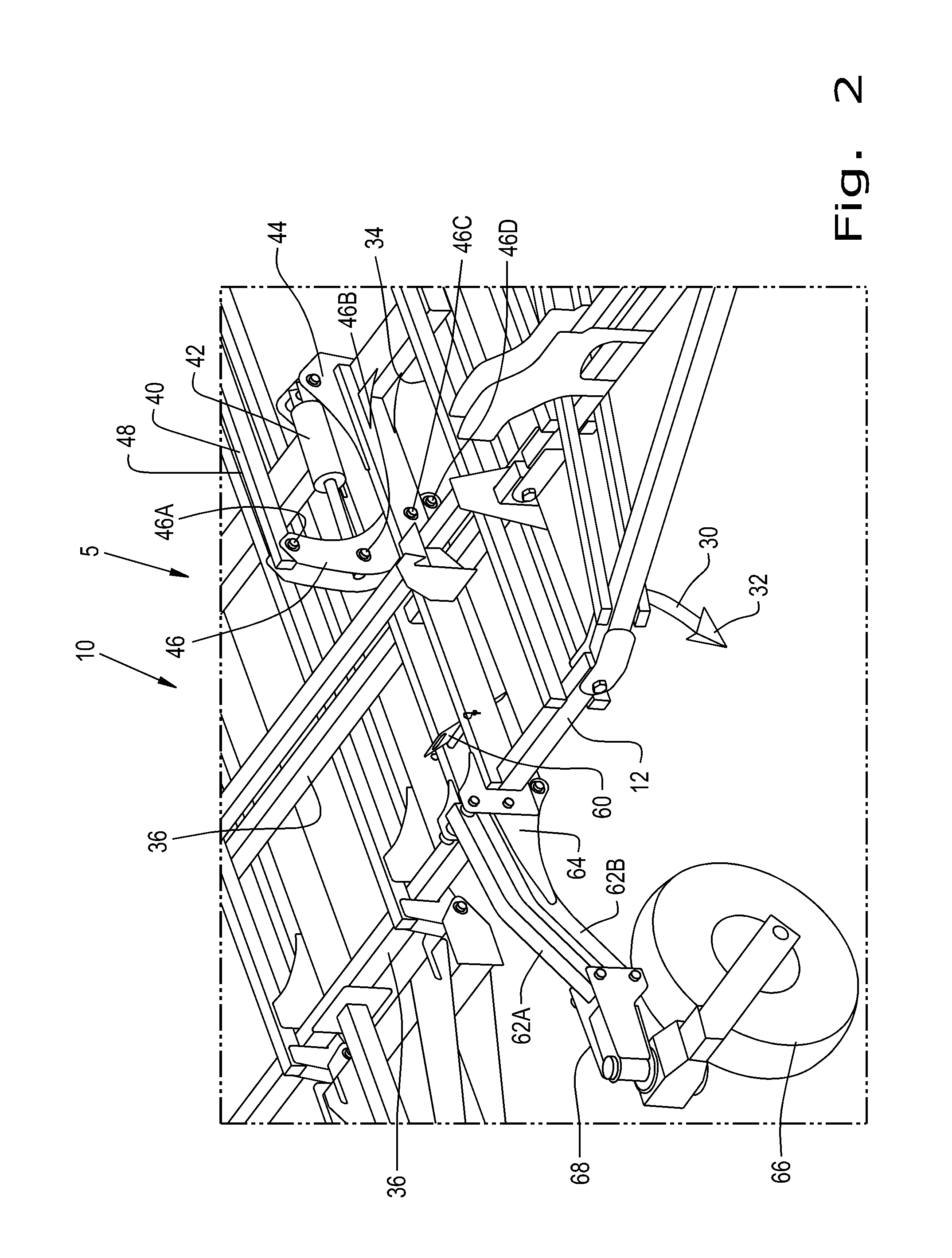
[0032]Referring now to the drawings, and more particularly to FIGS. 1-4, there is shown an embodiment of an agricultural tillage implement 5 of the present invention. In the illustrated embodiment, the tillage implement 5 is in the form of a field cultivator 10 for tilling and finishing soil prior to seeding. Field cultivator 10 is configured as a multi-section field cultivator, and includes a center frame section 12 and at least one wing frame section 14 (not shown in FIGS. 1-4). Center frame section 12 is the center section that is directly towed by a traction unit, such as an agricultural tractor (not shown), in a travel direction 22. A pull hitch 18 extends forward from center frame section 12, and is coupled with the traction unit in known manner.

[0033]Center frame section 12 and wing frame section 14 generally function to carry cultivator shanks 30 with shovels 32 at their lower ends for tilling the soil. Center frame section 12 and wing frame section 14 both include longitudi...


PUM


Abstract

A lift and gauge wheel lift mechanism has a hydraulic lift cylinder pivotally connected to a lift mechanism rocker link. A rear lift wheel link is pivotally connected to the lift mechanism rocker link. The rear lift wheel link is pivotally connected to either a rear lift wheel arm having at least one rear lift wheel attached. A gauge wheel link is pivotally connected to the lift mechanism rocker link. The gauge wheel link is pivotally connected to a gauge wheel parallel arm bell crank. The gauge wheel parallel arm bell crank is attached to either a gauge wheel upper parallel arm, or to a gauge wheel lower parallel arm. At least one front gauge wheel is connected to the gauge wheel upper parallel arm and to the gauge wheel lower parallel arm.

Description

CROSS REFERENCE TO RELATED APPLICATIONS[0001]This is a continuation-in-part of U.S. patent application Ser. No. 14 / 537,206, entitled “ROCKER LINK LIFT SYSTEM”, filed Nov. 10, 2014, which is incorporated herein by reference.BACKGROUND OF THE INVENTION[0002]1. Field of the Invention[0003]The present invention relates to agricultural implements, and, more particularly, to lift mechanisms for agricultural tillage implements.[0004]2. Description of the Related Art[0005]Farmers utilize a wide variety of tillage implements to prepare soil for planting. Some such implements include two or more sections coupled together to perform multiple functions as they are pulled through fields by a tractor. For example, a field cultivator is capable of simultaneously tilling soil and leveling the tilled soil in preparation for planting. A field cultivator has a frame that carries a number of cultivator shanks with shovels at their lower ends for tilling the soil. The field cultivator converts compacted...

Claims


Application Information

Patent Timeline
Patent Type & Authority Applications(United States)
IPC IPC(8): A01B63/22A01B59/042A01B63/00
CPCA01B63/22A01B63/002A01B73/044A01B19/02A01B59/042
Inventor SUDBRINK, MATTHEW R.KNOBLOCH, DEAN A.
Owner BLUE LEAF I P INC
Learn More