
Equatorial Support for Telescope

Inactive Publication Date: 2010-04-08
BERCELLA FRANCO
View PDF21 Cites 12 Cited by
  • Summary
  • Abstract
  • Description
  • Claims
  • Application Information

AI Technical Summary

Benefits of technology

[0014]The problem at the heart of the present invention is thus to provide a support for telescopes which is characterized by being easily transported, free of cantilevered parts (and thus free of the vibrations generating therefrom) and by a perfect weight balance, such that relatively large-sized amateur telescopes are also made transportable.

Problems solved by technology

This movement is very complicated, and together with the rotation of the field of view during the movement, a prerequisite condition is also the constant movement of both motors relative to the two axes of movement (azimuth and altitude) in addition to a sophisticated automation (the so-called field derotator), which is normally inaccessible to beginners and amateur astronomers in general because of the high cost.
The loads of the optical components are thus unbalanced to the North relative to the basement supporting the telescope.
Fork mounts also consist of a cantilever framework, with loads unbalanced to the North relative to the barycentre of the basement supporting the telescope.
The framework stiffening, to the purpose of restraining the inevitable vibrations of the cantilevered parts (the equatorial head and the fork), is only obtained by making the basement heavier, thus making the assembly more difficult to transport and also more expensive.
English mount, however, has a drawback that makes it inapplicable to amateur telescopes: the two piers holding the frame along which the RA axis passes must be especially manufactured according to the latitude of the observatory location.
Furthermore, since it requires two support piers or frames, this mount is very bulky and heavy.
These characteristics make the English mount non-transportable, even if it were built in a size suitable for an amateur telescope.
Therefore, while on the one hand, a small size and a light weight are a selection factor for a telescope mount, on the other hand, whenever the latter has to be transported to a different place, the latitude requires to be adjusted, which cannot be done with English mounts.

Method used


Image

  • Equatorial Support for Telescope
  • Equatorial Support for Telescope
  • Equatorial Support for Telescope

Examples


Embodiment Construction

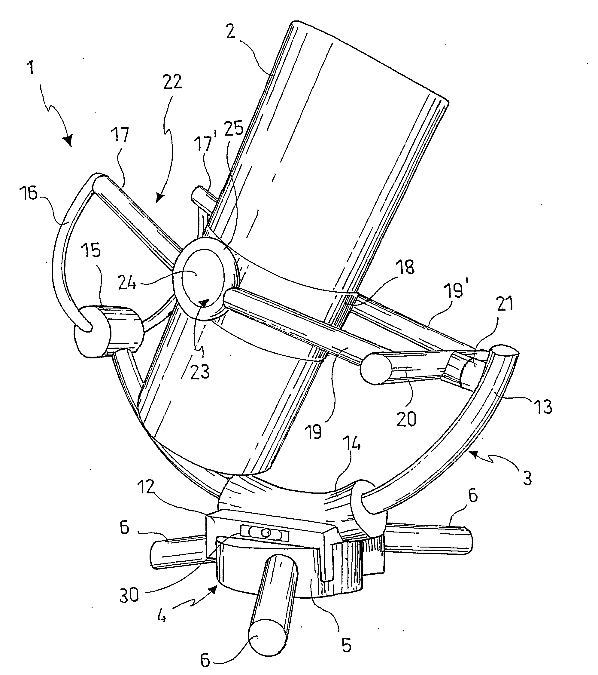
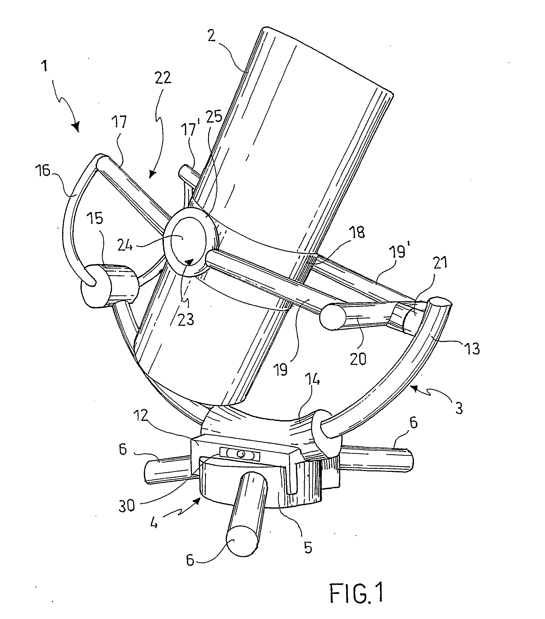
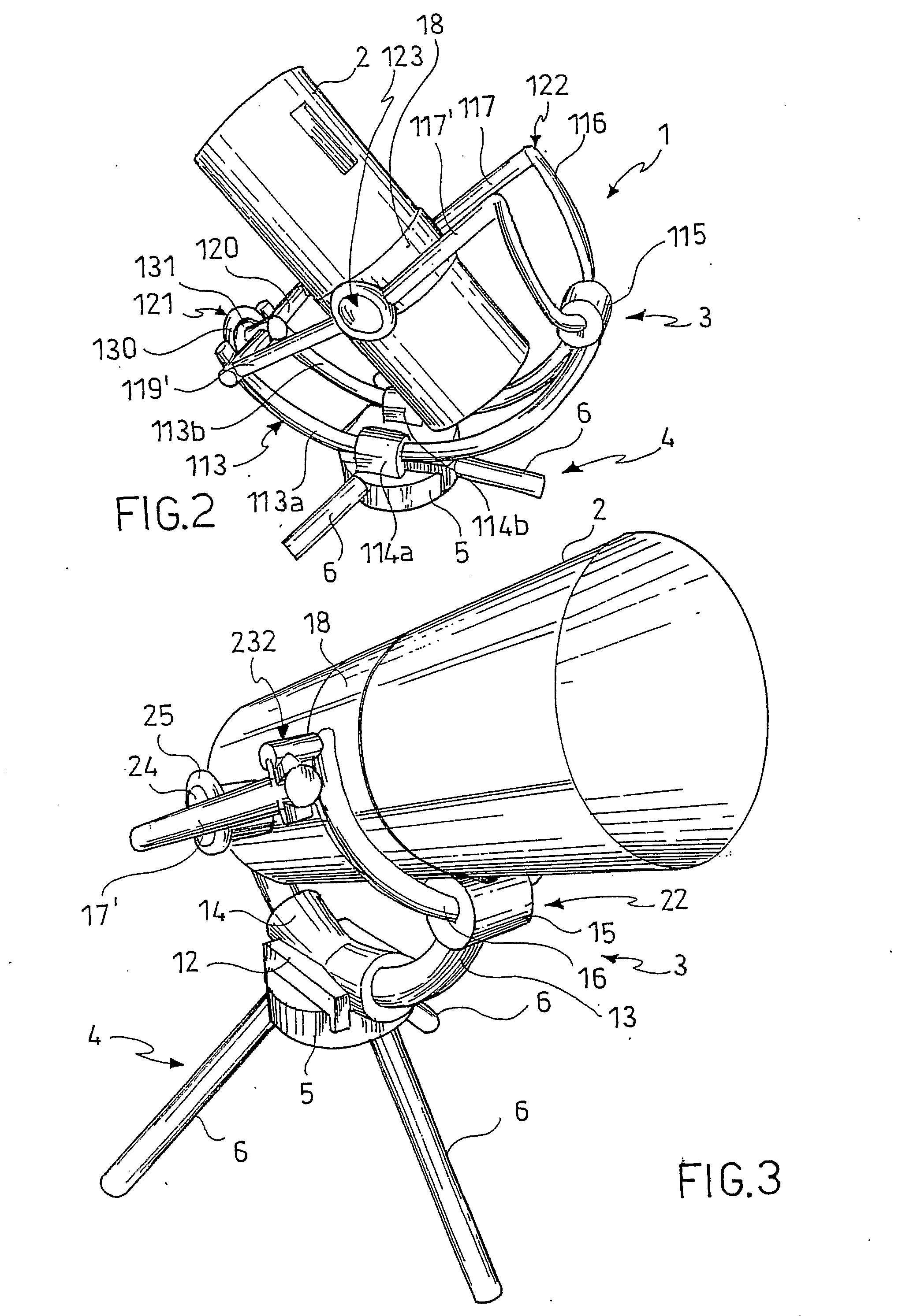
[0044]With reference to the figures, the support of the invention for a telescope 2 is generally indicated with 1.

[0045]The telescope 2, which is schematically illustrated in form of a cylinder, can be of any type, though preferably will be a reflector telescope, such as a Newton, Dobson, Cassegrain, Schmidt-Cassegrain, catadioptric telescope, and variants thereof. This type of telescopes comprises a primary mirror, of which the diameter, focal length and optical configuration determine the luminosity and contrast of the image, and a more or less complicated optical system that conveys the image to an eyepiece, which will be responsible for the magnification thereof. As compared with refractor telescopes, reflection telescopes can be made with larger optics, while maintaining compactness and lightness. Furthermore, they are much less expensive than refractor ones, at the same optical aperture, and thus are the ones which are commonly selected by amateur users.

[0046]The support 1 com...


PUM


Abstract

The present invention relates to a mount for telescopes, particularly of a portable type for amateur or semi-amateur telescopes, though it can be also applied to fixed telescopes and professional telescopes.Particularly, the present invention relates to a support for a telescope comprising a mount and means for resting said mount on the ground, wherein said mount comprises a primary rocking element allowing one to set the latitude of the observation place, to said primary rocking element being pivotally fastened a frame which allows moving the telescope about the right ascension axis and / or about the declination axis.

Description

FIELD OF THE INVENTION[0001]The present invention relates to a support for telescopes, particularly of a portable type for amateur or semi-amateur telescopes, though it can be also applied to fixed telescopes and professional telescopes.BACKGROUND OF THE INVENTION[0002]Various types of supports or mounts for telescopes are available. According to a first general classification, mounts can be divided into altazimuth mounts and equatorial mounts.[0003]In altazimuth mounts, the two axes about which the telescope can move are the one orthogonal and the other parallel to the ground, such that the optics can move in all the directions along Cartesian axes. However, this arrangement of the axes of movement does not correspond to the arrangement of the Earth's axis and equatorial plane, which, as is known, at other latitudes than the poles are inclined relative thereto. Consequently, due to the Earth's true motion (spin about the North-South polar axis in the West-East direction), the optic...

Claims


Application Information

Patent Timeline
IPC IPC(8): G02B23/16
CPCG02B23/165
Inventor LOPRESTI, CLAUDIO
Owner BERCELLA FRANCO
Learn More