Optical imaging lens

Active Publication Date: 2019-07-18
GENIUS ELECTRONICS OPTICAL CO LTD
View PDF0 Cites 2 Cited by
  • Summary
  • Abstract
  • Description
  • Claims
  • Application Information

AI Technical Summary

Benefits of technology

The invention provides an optical imaging lens that has excellent optical performance. By controlling the arrangement and refracting power of specific lens elements, and meeting certain conditions, the lens can capture images with a large field of view and short system length.

Problems solved by technology

Nevertheless, the imaging quality of optical lens assemblies for vehicles still falls behind the imaging quality of optical lens assemblies for mobile phones.
How to facilitate the imaging quality of lenses for vehicles under the premise of maintaining a large aperture, a large field of view, and a short lens length has become a popular issue in the industry.
However, when designing an optical imaging lens, an optical lens having both a miniaturized size and a desirable imaging quality cannot be manufactured by simply scaling down a lens with a desirable imaging quality.
How to manufacture a miniaturized optical imaging lens meeting the needs of consumer electronic products and facilitate the imaging quality of such optical imaging lens has been an issue of this field.

Method used


Image

  • Optical imaging lens
  • Optical imaging lens
  • Optical imaging lens

Examples


first embodiment

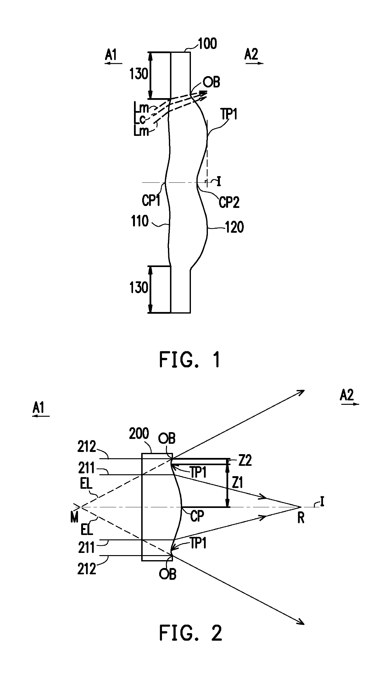
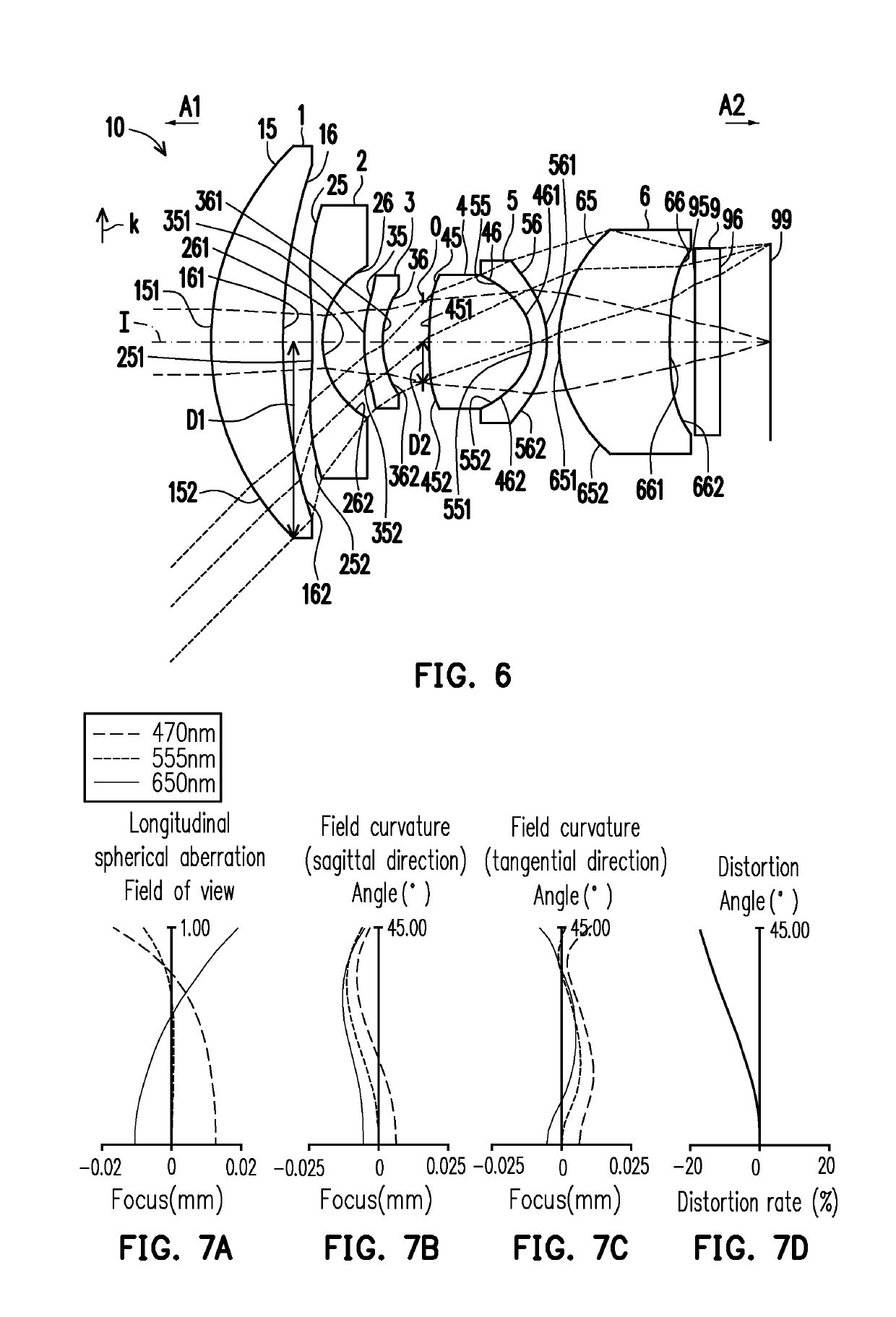
[0079]In the first embodiment, the aperture stop 0 is disposed between the third lens element 3 and the fourth lens element 4. The aperture stop 0 has a radius D2. The radius D2 of the aperture stop 0 refers to a distance between an optical boundary (i.e., a point where a radially outermost marginal ray passing through the aperture stop 0 intersects the aperture stop 0) of the aperture stop 0 and the optical axis I of the optical imaging lens 10 in a radial direction k. In addition, the radial direction k is perpendicular to the optical axis I.

[0080]The fourth lens element 4 has positive refracting power. An optical axis region 451 of the object side surface 45 of the fourth lens element 4 is convex, and a periphery region 452 of the object side surface 45 of the fourth lens element 4 is convex. An optical axis region 461 of the image side surface 46 of the fourth lens element 4 is convex, and a periphery region 462 of the image side surface 46 of the fourth lens element 4 is convex...

second embodiment

[0144]Respective aspheric coefficients of the object side surface 25 of the second lens element 2 to the image side surface 66 of the sixth lens element 6 of the second embodiment in Equation (1) are as shown in FIG. 13.

[0145]In addition, relations of important parameters in the optical imaging lens 10 according to the second embodiment are as shown in FIGS. 46 and 47.

[0146]The longitudinal spherical aberration of the second embodiment is shown in FIG. 11A, and imaging point deviations of the off-axis rays in different heights are controlled within a range of ±0.025 mm. In FIGS. 11B and 11C illustrating the astigmatic field curves, focal distance variations of the three representing wavelengths in the whole field range fall within ±0.025 mm. The distortion aberration shown in FIG. 11D indicates that the distortion aberration of the second embodiment is maintained within a range of ±10%.

[0147]Based on the above, the Fno of the second embodiment is less than the Fno of the first embod...

third embodiment

[0150]Respective aspheric coefficients of the object side surface 25 of the second lens element 2 to the image side surface 66 of the sixth lens element 6 of the third embodiment in Equation (1) are as shown in FIG. 17.

[0151]In addition, relations of important parameters in the optical imaging lens 10 according to the third embodiment are as shown in FIGS. 46 and 47.

[0152]The longitudinal spherical aberration of the third embodiment is shown in FIG. 15A, and imaging point deviations of the off-axis rays in different heights are controlled within a range of ±0.025 mm. In FIGS. 15B and 15C illustrating the astigmatic field curves, focal distance variations of the three representing wavelengths in the whole field range fall within ±0.050 mm. The distortion aberration shown in FIG. 15D indicates that the distortion aberration of the third embodiment is maintained within a range of ±8%.

[0153]Based on the above, the distortion aberration of the third embodiment is less than the distortion...


PUM


Abstract

An optical imaging lens sequentially includes a first, a second, a third, a fourth, a fifth, and a sixth lens elements from an object side to an image side along an optical axis. Each of the lens elements includes an object-side surface and an image-side surface. The second lens element has negative refracting power. A periphery region of the object-side surface of the fourth lens element is convex. A periphery region of the image-side surface of the fifth lens element is convex. The optical imaging lens satisfies following conditions: HFOV≤45°; 2.000≤D1 / D2, and TTL / T6≤6.300.

Description

CROSS-REFERENCE TO RELATED APPLICATION[0001]This application claims the priority benefit of Chinese application serial no. 201810035609.0, filed on Jan. 15, 2018. The entirety of the above-mentioned patent application is hereby incorporated by reference herein and made a part of this specification.BACKGROUND OF THE INVENTION1. Field of the Invention[0002]The invention relates to an optical device, and particularly relates to an optical imaging lens.2. Description of Related Art[0003]As portable electronic products with novel specifications emerge one after another, the development of a crucial part, i.e., the optical imaging lens, is also diversified. There are more and more applications of optical lens assemblies in vehicle-related fields, such as car-backing systems, 360 degree panoramic systems, lane departure warning systems, rear surveillance systems, and advanced driver assistance systems (ADAS). One vehicle may include 6 to 20 optical lens assemblies, and the specifications o...

Claims


Application Information

Patent Timeline
IPC IPC(8): G02B9/62G02B27/00
CPCG02B9/62G02B27/0037G02B13/0045G02B13/06G02B13/18G02B3/04G02B13/04
Inventor CHEN, YU-MINGWANG, PEI-CHIHSU, SHENG-WEI
Owner GENIUS ELECTRONICS OPTICAL CO LTD
Why Eureka
Try Eureka