Check patentability & draft patents in minutes with Patsnap Eureka AI!

Linear solid-state lighting with multiple switches

Active Publication Date: 2019-08-20
ALEDDRA INC
View PDF4 Cites 2 Cited by
  • Summary
  • Abstract
  • Description
  • Claims
  • Application Information

AI Technical Summary

Benefits of technology

The patent describes a replacement for a fluorescent lamp that can be used in a retrofit or new lamp fixture. The replacement, called the LL lamp, can work with existing ballasts or AC mains configurations. When installed, the LL lamp detects how the electric voltage is applied and controls the flow of electric current. This ensures that the lamp operates safely and without any uncertainty. The technical effect of this patent is the replacement of a potentially dangerous fluorescent lamp with a safer and more versatile LL lamp.

Problems solved by technology

No electric shock is possible to occur for all the above configurations during initial installation and re-lamping.

Method used


Image

  • Linear solid-state lighting with multiple switches
  • Linear solid-state lighting with multiple switches
  • Linear solid-state lighting with multiple switches

Examples


Embodiment Construction

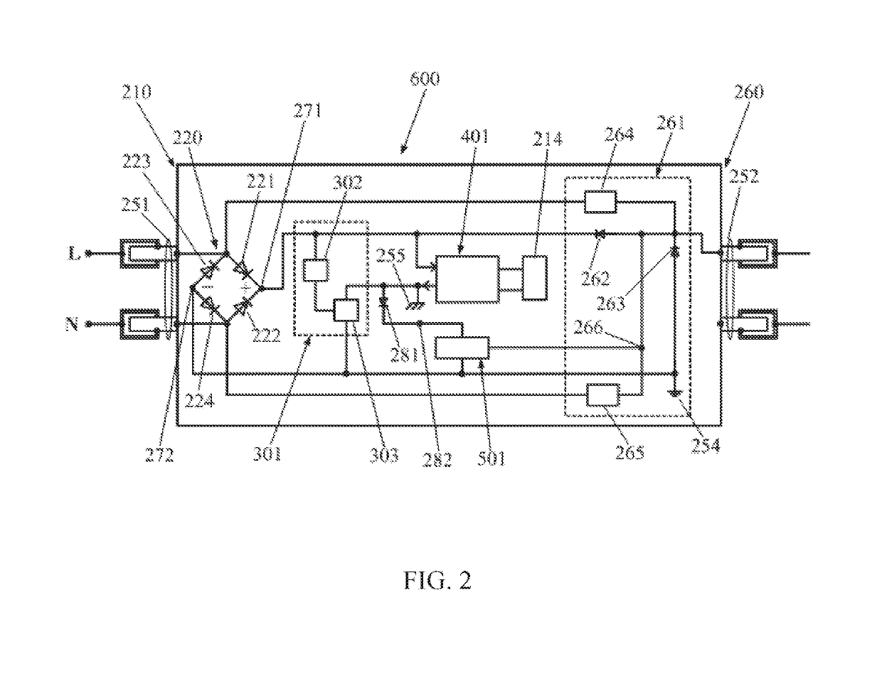
[0023]FIG. 1 is a block diagram of a linear LED lamp operable with the AC mains in the double ends according to the present disclosure. The LL lamp 600 comprises a housing having a front end 210 and a rear end 260; one or more LED arrays 214 with a forward voltage across thereon; a first bi-pin 251 and a second bi-pin 252 respectively coupled to the front end 210 and the rear end 260, protruding outwards to receive an input AC voltage; an anti-electric-shock module 301; at least one switch control module 501; a front-end module 220 and a rear-end module 261; and an LED driving circuit 401. The front-end module 220 comprises four front-end diodes 221, 222, 223, and 224 connected as a full-wave rectifier with a high DC voltage potential port 271 and a low DC voltage potential port 272. The low DC voltage potential port 272 is connected to a first ground reference 254, also denoted as “-” in the full-wave rectifier. The front-end module 220 is coupled to the first bi-pin 251 and the fi...


PUM


Abstract

A linear light-emitting diode (LED) lamp (LL lamp) comprising a front-end module, an LED driving circuit operable with a ballast and alternate current (AC) mains, an anti-electric-shock module, and a switch control module operates with the AC mains in a single end and double ends and with the ballast in the double ends without any risk of electric shock. Besides, the LL lamp passes an industry required electric shock test when an input AC voltage from a testing ballast is applied in the double ends. Whereas both the front-end module and the switch control module are coupled to a first ground reference, the LED driving circuit is coupled to a second ground reference. When the input AC voltage from the ballast is applied, the switch control module is enabled to couple the second ground reference to the first ground reference, allowing a current returned to operate the LL lamp.

Description

CROSS-REFERENCE TO RELATED APPLICATIONS[0001]The present disclosure is part of a continuation-in-part (CIP) application of U.S. patent application Ser. No. 16 / 401,849, filed 2 May 2019, which is part of CIP application of U.S. patent application Ser. No. 16 / 296,864, filed 8 Mar. 2019, which is part of CIP application of U.S. patent application Ser. No. 16 / 269,510, filed 6 Feb. 2019, which is part of CIP application of U.S. patent application Ser. No. 16 / 247,456, filed 14 Jan. 2019, which is part of CIP application of U.S. patent application Ser. No. 16 / 208,510, filed 3 Dec. 2018 and issued as U.S. Pat. No. 10,237,946 on 19 Mar. 2019, which is part of CIP application of U.S. patent application Ser. No. 16 / 154,707, filed 8 Oct. 2018 and issued as U.S. Pat. No. 10,225,905 on 5 Mar. 2019, which is part of a CIP application of U.S. patent application Ser. No. 15 / 947,631, filed 6 Apr. 2018 and issued as U.S. Pat. No. 10,123,388 on 6 Nov. 2018, which is part of a CIP application of U.S. pa...

Claims


Application Information

Patent Timeline
IPC IPC(8): H05B33/08H05B44/00
CPCH05B33/089H05B33/0815Y02B20/30H05B45/375H05B45/3578
Inventor HSIA, CHUNGHO
Owner ALEDDRA INC
Features
  • R&D
  • Intellectual Property
  • Life Sciences
  • Materials
  • Tech Scout
  • Unparalleled Data Quality
  • Higher Quality Content
  • 60% Fewer Hallucinations
Learn More