Ultra-low power and cost purely analog backscatter sensors with extended range smartphone/consumer electronics FM reception

a technology of backscatter and wireless sensors, applied in the field of ultra-low power and cost wireless sensors, can solve the problems of increasing the monetary (in euros) and power cost (in watts) per wireless sensor, increasing the cost of energy storage devices, and increasing the number of such wireless sensors. , to achieve the effect of boosting the communication range of the device, low power consumption, and convenient maintenance and operation

Active Publication Date: 2019-08-27
VOUGIOUKAS GEORGIOS +1
View PDF8 Cites 1 Cited by
  • Summary
  • Abstract
  • Description
  • Claims
  • Application Information

AI Technical Summary

Benefits of technology

[0007]The objective of the present invention is achieved by a backscatter sensor device that implements ultra-low power and cost, purely analog backscatter sensors of capacitive or resistive primitives, which generate signals able to be received by commodity FM receivers, typically found in consumer electronics or smartphones. The backscatter sensor device offers extended communication range in the order of tens of meters, with power consumption (under continuous operation) below 24 μW, using no ADC, DLC or MCU. It can accommodate a large variety of capacitive or resistive elements, it is easy to maintain and operate from a non-skilled person. The objective of the present invention is also achieved by a receiving device and device method, which boosts the communication range of the device.

Problems solved by technology

Large numbers of such wireless sensors require an extensive amount of money to acquire, install, operate and maintain.
Moreover, their power consumption in continuous operation may not allow for batteryless operation or may require battery replacements periodically, or may increase cost for energy storage devices, such as supercapacitors.
Such designs increase monetary (in Euros) and power cost (in Watt) per wireless sensor, while they require a dedicated wireless receiver of the sensed and wirelessly-transmitted information.
Dedicated emitters or receivers for scatter radio increase the overall monetary cost to assembly, operate and maintain scatter radio infrastructure.
Scatter radio-based sensors may also suffer from limited communications range.
Furthermore, MCU and / or DLC and / or ADC increase complexity and thus, monetary and power cost per wireless sensor.

Method used


Image

  • Ultra-low power and cost purely analog backscatter sensors with extended range smartphone/consumer electronics FM reception
  • Ultra-low power and cost purely analog backscatter sensors with extended range smartphone/consumer electronics FM reception
  • Ultra-low power and cost purely analog backscatter sensors with extended range smartphone/consumer electronics FM reception

Examples


Embodiment Construction

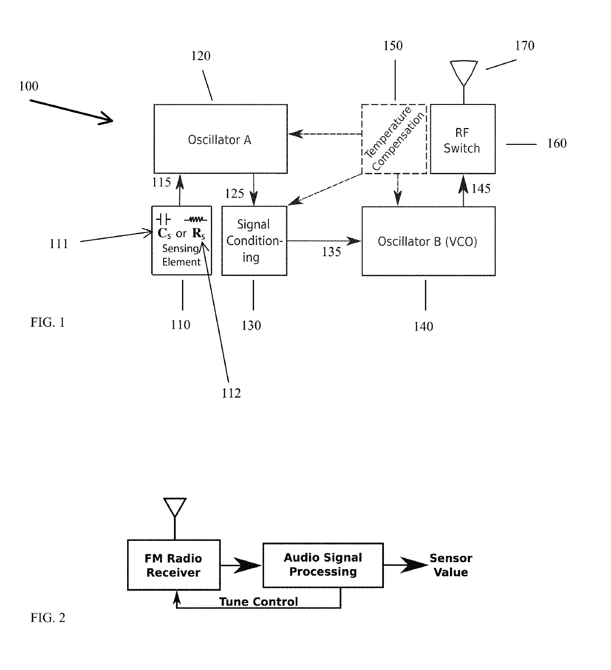
[0019]FIG. 1 depicts a backscatter sensor device 100 according to examples of the invention. Backscatter sensor device 100 may comprise a sensing circuit 110, a first oscillator 120, a signal conditioning circuit 130, a second oscillator 140, a temperature compensation device 150, a Radio Frequency (RF) switch 160 and an antenna 170.

[0020]Sensing circuit 110 may be implemented as a sensing element comprising by a single sensing capacitor Cs 111, or a sensing resistor Rs 112, or combinations thereof. Sensing circuit 110 may measure soil moisture or air humidity or pressure or other similar quantities, or combinations thereof. Sensing circuit 110 may be connected to the first oscillator 120. In some examples, sensing circuit 110 may comprise a plurality of sensing elements connected in series, or in parallel or in combinations thereof. In some examples, sensing elements may be of different technologies and / or of different tolerances and / or measure different ranges and / or measure diffe...


PUM


Abstract

Ultra-low power and cost, purely analog backscatter sensors, based on capacitive and / or resistive principles, consumer electronics FM reception and extended range.

Description

TECHNICAL FIELD[0001]Aspects herein relate generally to ultra-low power and cost wireless sensors. More particularly, aspects herein relate to a backscatter sensor device comprising purely analog capacitive or resistive sensors. The backscatter sensor device requires less than 24 μWatt in continuous operation to perform and transmit measurements that can be received by conventional FM receivers, typically found in smartphones or commodity electronics. The backscatter sensor device offers communication range up to 26 meters outdoors, can accommodate a large variety of capacitive or resistive elements, and is easy to maintain and operate from a non-skilled person. Aspects also relate to a receiver device and method for boosting the communication range of the wireless sensing device.BACKGROUND OF THE INVENTION[0002]Measuring and wirelessly transmitting temperature, air / environmental humidity, soil moisture or pressure with ultra-low monetary cost (in dollars), as well as ultra-low powe...

Claims


Application Information

Patent Timeline
Patent Type & Authority Patents(United States)
IPC IPC(8): G06K19/07G06K19/077H04B1/12H04B1/10
CPCH04B5/0031Y02D30/70G06K19/07773H04B1/10H04B1/12
Inventor VOUGIOUKAS, GEORGIOSBLETSAS, AGGELOS
Owner VOUGIOUKAS GEORGIOS
Why Eureka
Try Eureka