Check patentability & draft patents in minutes with Patsnap Eureka AI!

Power storage module

a technology of power storage module and power storage module, which is applied in the direction of cell components, electrical apparatus, electrochemical generators, etc., can solve the problems of increasing manufacturing costs, and achieve the effect of reducing the cooling efficiency of the cooling member 13, increasing the pressure inside the enclosing member, and increasing the volume of the enclosing member 26

Active Publication Date: 2019-08-27
AUTONETWORKS TECH LTD +2
View PDF10 Cites 0 Cited by
  • Summary
  • Abstract
  • Description
  • Claims
  • Application Information

AI Technical Summary

Benefits of technology

[0005]According to the above structure, the pipe needs to be strong to seal the heat transfer fluid therein because the heat transfer fluid that receives heat from a heating element is evaporated and increases its volume and pressure within the pipe is increased. If the pipe that is relatively strong and encloses the heat transfer fluid therein in a fluid tight manner is used, a manufacturing cost may be increased.
[0007]However, according to the above-described assumptive technology, according to the evaporation of the refrigerant, the pressure within the enclosing member is increased and the sheet members are expanded. Then, liquefied refrigerant may remain inside the expanded sheet members. The refrigerant remaining inside the sheet members do not work for cooling and the cooling properties of the cooling member may be lowered.
[0012]The cooling member is arranged to be inclined with respect to the horizontal plane such that the section thereof being in contact with the power storage element to transfer heat is on the lower level. With such a configuration, the refrigerant that is made into liquid flows downward within the enclosing member and moves to the section where the cooling member and the power storage element are contacted to transfer heat. Accordingly, the refrigerant that does not work for cooling is less likely to remain in the cooling member and the cooling properties of the cooling member can be improved.
[0015]According to the above configuration, the cooling properties of the power storage module can be improved.
[0017]According to the above configuration, the refrigerant that is liquefied inside the cooling member surely flows down within the cooling member and moves to the section where the cooling member and the power storage element are in contact with each other to transfer heat therebetween. Accordingly, the cooling properties of the cooling member can be surely improved.
[0018]According to the present technology described in this specification, cooling properties of a cooling member is improved.

Problems solved by technology

If the pipe that is relatively strong and encloses the heat transfer fluid therein in a fluid tight manner is used, a manufacturing cost may be increased.

Method used


Image

  • Power storage module
  • Power storage module
  • Power storage module

Examples


first embodiment

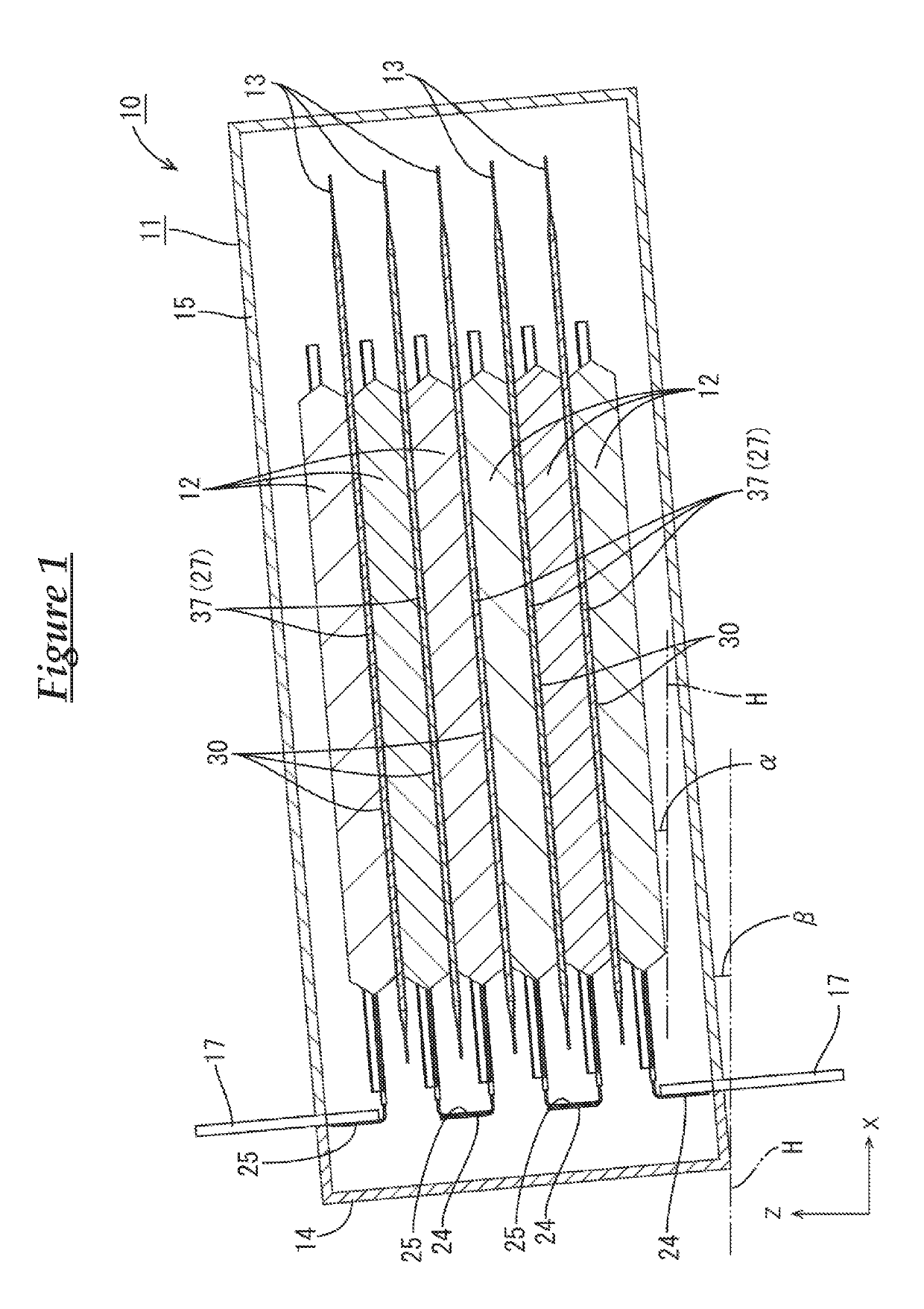
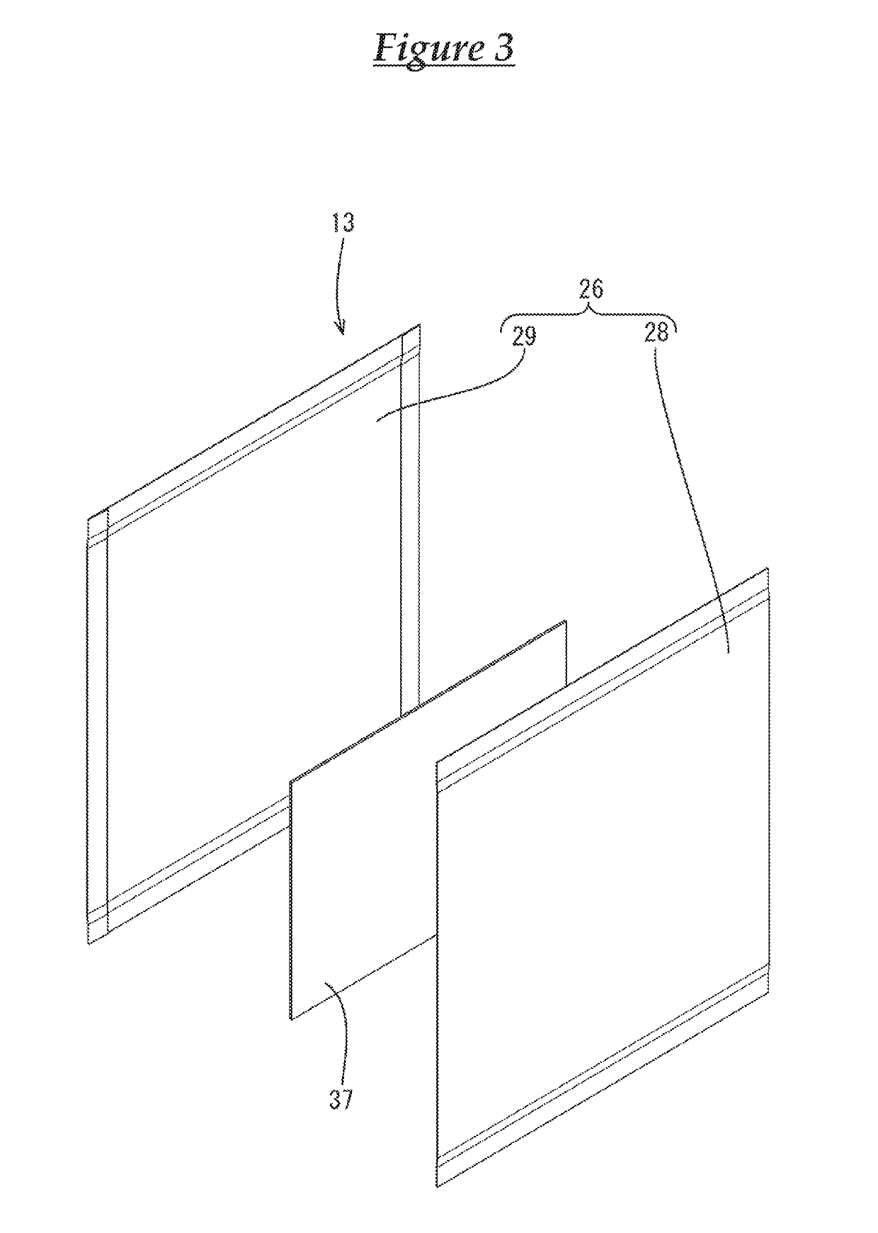
[0027]A first embodiment according to a technology described in this specification will be described with reference to FIGS. 1 to 7. A power storage module 10 according to this embodiment includes a casing 11, power storage elements 12 arranged in the casing 11, and cooling members 13 that are arranged in the casing 11 and in contact with a part of an outer surface of each of the power storage elements 12. In the following description, an X direction represents a right side, a Y direction represents a front side, and a Z direction represents an upper side. Symbols or numerals are put on one or some of the parts having the same shape and no symbols or numerals may be put on the rest of them.

[0028]As illustrated in FIG. 1, the casing 11 is a substantially rectangular parallelpiped shape as a whole. The casing 11 includes a first case 14 and a second case 15. The first case 14 is open toward a right side and has a substantially rectangular shape seen from the right side. The second cas...

examples

[0059]Next, Examples 1 to 3 representing effects of the technology described in this specification will be described with reference to FIGS. 5 to 7. A cooling member used in each of Examples 1 to 3 was made as follows. A sheet member of polyethylene was cut into pieces of 120 mm×170 mm. Two sheet members were overlapped while having 10 ml of refrigerant and a non-woven cloth cut into a piece of 118 mm×150 mm therebetween. Then, the edges of the two sheet members are joined with welding to be sealed in a liquid tight manner. The refrigerant is Novec 649 (registered trademark) made by 3M Japan (hereinafter, referred to as refrigerant).

[0060]An electric heater of 10 cm×10 cm was pressed on one surface of the cooling member. The heater was pressed against the cooling member with pressure of 0.2 Pa. The heater was supplied with heat quantity of 12 W. The temperature sensor was arranged between the heater and the cooling member. The measured temperature represents temperature of a surface...


PUM

PropertyMeasurementUnit
angleaaaaaaaaaa
heightaaaaaaaaaa
angleaaaaaaaaaa

Abstract

A power storage module includes power storage elements and cooling members that are in contact with the power storage elements to transfer heat. The cooling member includes an enclosing member, refrigerant, and an absorbing member absorbing the refrigerant, and the enclosing member includes a first sheet member and a second sheet member that are connected in a liquid tight manner, and the refrigerant and the absorbing member are arranged within the enclosing member. The cooling member is arranged to be inclined with respect to a horizontal plane such that a section thereof being in contact with the power storage element to transfer heat is on a lower level.

Description

CROSS REFERENCE TO RELATED APPLICATIONS[0001]This application claims the priority of Japanese patent application JP2015-235680 filed on Dec. 2, 2015, the entire contents of which are incorporated herein.TECHNICAL FIELD[0002]The present technology relates to a technology of cooling a power storage module.BACKGROUND ART[0003]A technology of cooling a power storage module has been known. A heat pipe described in Patent Document 1 has been known. Such a heat pipe includes a pipe made of metal and heat transfer fluid filled in the heat pipe in a fluid tight manner.[0004][Patent Document 1] Japanese Unexamined Patent Application Publication No. 11-23169SUMMARY[0005]According to the above structure, the pipe needs to be strong to seal the heat transfer fluid therein because the heat transfer fluid that receives heat from a heating element is evaporated and increases its volume and pressure within the pipe is increased. If the pipe that is relatively strong and encloses the heat transfer fl...

Claims


Application Information

Patent Timeline
Patent Type & Authority Patents(United States)
IPC IPC(8): H01M10/652H01M10/647H01M2/10H01M10/6555H01M10/613H01M10/6552H01M10/6569H01M50/211
CPCH01M10/647H01M10/6555H01M10/613H01M10/6552Y02E60/10H01M50/211H01M10/6569H01M10/652
Inventor KUBOKI, HIDEYUKIHIRAI, HIROKIHIGASHIKOZONO, MAKOTOHOSOE, AKIHISATAKEYAMA, TOMOHARUHIROSE, YOSHIYUKI
Owner AUTONETWORKS TECH LTD
Features
  • R&D
  • Intellectual Property
  • Life Sciences
  • Materials
  • Tech Scout
  • Unparalleled Data Quality
  • Higher Quality Content
  • 60% Fewer Hallucinations
Learn More