Dynamic transaction card with EMV interface and method of manufacturing

a technology of dynamic transaction card and emv interface, which is applied in the field of dynamic transaction card, can solve the problems of limited size and location of other components of the smart card, such as display components and sensors, and the thickness of the card, and achieve the optimal location of specific locations

Active Publication Date: 2019-09-10
CAPITAL ONE SERVICES
View PDF130 Cites 0 Cited by
  • Summary
  • Abstract
  • Description
  • Claims
  • Application Information

AI Technical Summary

Benefits of technology

[0007]A dynamic transaction card with an EMV interface may be manufactured using a separate printed circuit board layout with EMV contact patterns placed into the top surface of a molding to create the dynamic transaction card. The edges of the EMV contact patterns may be incorporated through holes, which are trimmed to scallops, to allow for surface mounting. The EMV interface may then include a connection between the EMV contact patterns and the EMV microprocessor such that the EMV microprocessor does not have to be placed directly beneath the EMV contact patterns. By freely placing the EMV microprocessor, such that the EMV microprocessor does not have to be placed directly beneath the EMV contact patterns, the landscape of the interior of the dynamic transaction card may be altered in order to optimize other components of the dynamic transaction card. For example, by relocating the EMV microprocessor, the power source (e.g., energy storage component) may be expanded, the display components may be relocated and expanded, and / or sensors may be relocated.

Problems solved by technology

Placing the EMV microprocessor directly beneath the EMV contact patterns, poses limitations on the size and location of other components of the smart card, such as the display components and the sensors, as well as on the thickness of the card.
This specific location may not be the optimal location for placing the EMV microprocessor directly beneath the contact patterns when trying to decrease thickness of the card.

Method used


Image

  • Dynamic transaction card with EMV interface and method of manufacturing
  • Dynamic transaction card with EMV interface and method of manufacturing
  • Dynamic transaction card with EMV interface and method of manufacturing

Examples


Embodiment Construction

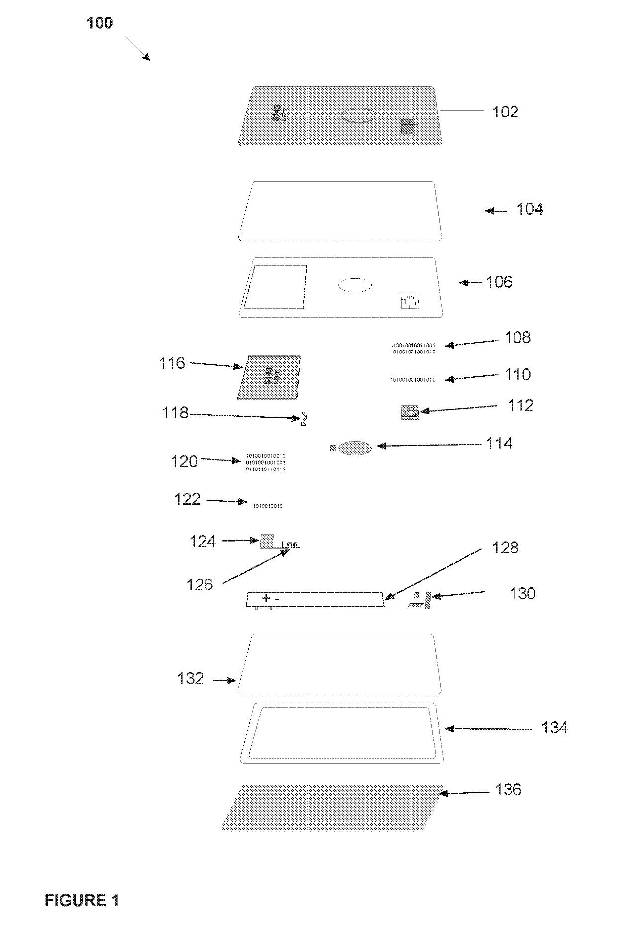
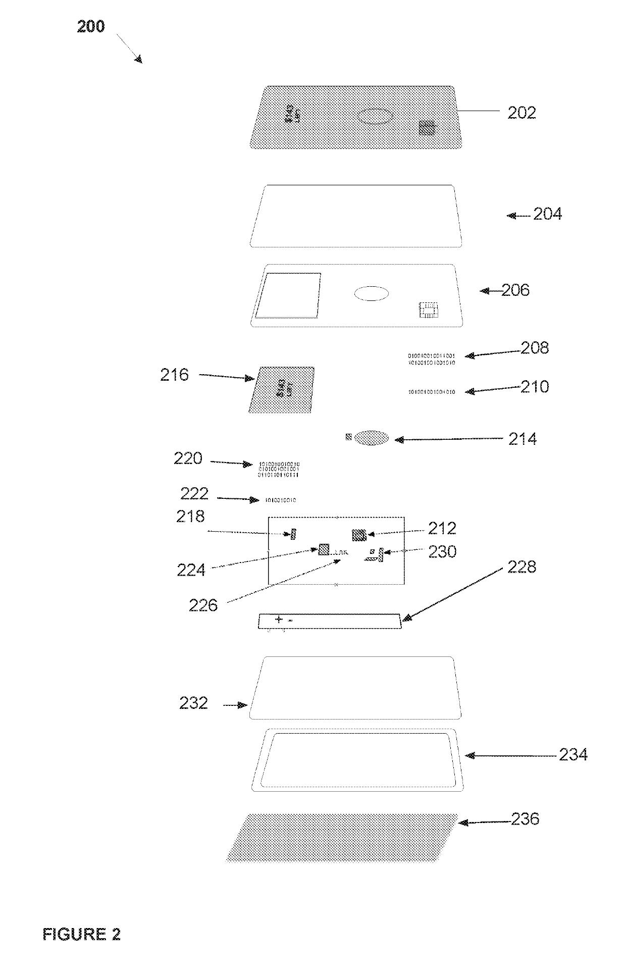
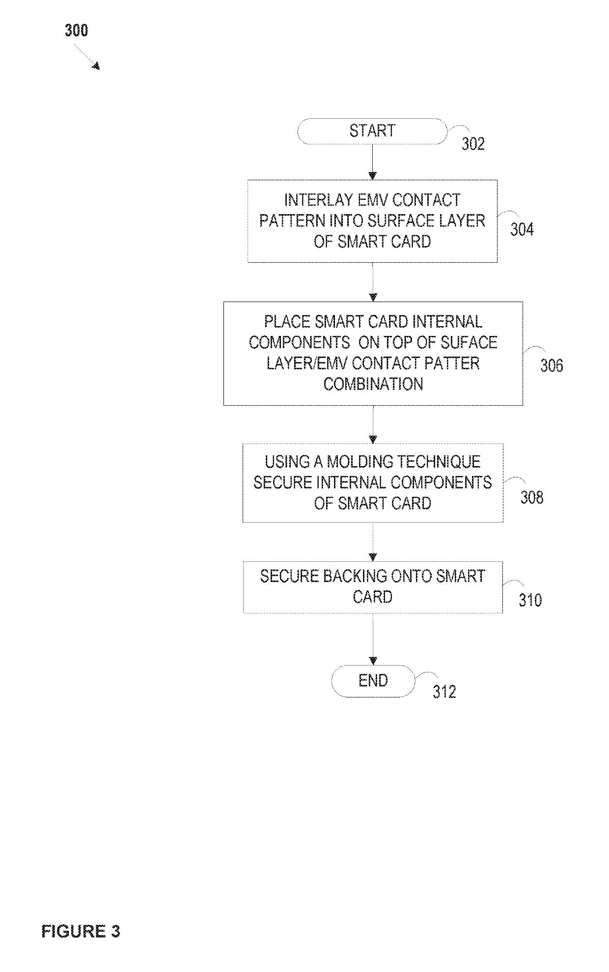
[0013]The following description is intended to convey a thorough understanding of the embodiments described by providing a number of specific exemplary embodiments and details involving a dynamic transaction card with EMV technology that includes an EMV interface connecting EMV contacts and an EMV processor to enable a multifunctional dynamic transaction card. It should be appreciated, however, that the present disclosure is not limited to these specific embodiments and details, which are exemplary only. It is further understood that one possessing ordinary skill in the art, in light of known systems and methods, would appreciate the use of the invention for its intended purposes and benefits in any number of alternative embodiments, depending on specific design and other needs. A financial institution and system supporting a financial institution are used as examples for the disclosure. The disclosure is not intended to be limited to financial institutions only. For example, many o...


PUM


Abstract

A dynamic transaction card with EuroPay-Mastercard-Visa (“EMV”) technology that includes an EMV interface connecting EMV contacts and an EMV processor to enable a multifunctional dynamic transaction card. A method of manufacturing a dynamic transaction card with an EMV interface connecting EMV contacts and an EMV processor. A dynamic transaction card with an EMV interface may be manufactured using a separate printed circuit board (PCB) layout with EMV contact patterns placed into the top surface of a molding to create the dynamic transaction card. The edges of the EMV contact patterns would be incorporated through holes, which are trimmed to scallops, to allow for surface mounting. The EMV interface may then include a connection between the EMV contact patterns and the EMV microprocessor such that the EMV microprocessor does not have to be placed directly beneath the EMV contact patterns.

Description

CROSS REFERENCE TO RELATED APPLICATIONS[0001]This application is a continuation of, and claims priority under 35 U.S.C. § 120 to, U.S. patent application Ser. No. 15 / 098,830 filed on Apr. 14, 2016, which claims the benefit of U.S. Provisional Application No. 62 / 270,648, entitled “Smart Card with EMV Interface and Method of Manufacturing,” filed Dec. 22, 2015 and benefit of U.S. Provisional Application No. 62 / 147,568, entitled “A System, Method, and Apparatus for a Dynamic transaction card,” filed Apr. 14, 2015. The entire contents of these applications are incorporated herein by reference.[0002]This application is related to U.S. application Ser. No. 15 / 098,935, entitled “Dynamic Transaction Card Power Management,” filed Apr. 14, 2016, which claims the benefit of U.S. Provisional Application No. 62 / 266,324, filed Dec. 11, 2015, U.S. Provisional Application No. 62 / 270,307 filed Dec. 21, 2015, and U.S. Provisional Application No. 62 / 305,599, filed Mar. 9, 2016. The entire contents of ...

Claims


Application Information

Patent Timeline
Patent Type & Authority Patents(United States)
IPC IPC(8): G07F7/10G06K19/077G06Q20/34
CPCG07F7/10G06K19/0772G06Q20/341G06K19/07724G06K19/07722
Inventor WURMFELD, DAVIDLOCKE, TYLERKOEPPEL, ADAM
Owner CAPITAL ONE SERVICES
Why Eureka
Try Eureka