
Universal Trendelenburg positioner

a positioner and trendelenburg technology, applied in the field of patient positioners, can solve the problems of patient slipping or sliding along the procedure table, affecting the procedure, and the patient is difficult to reposition

Active Publication Date: 2019-09-17
MEDLINE IND LP
View PDF20 Cites 3 Cited by
  • Summary
  • Abstract
  • Description
  • Claims
  • Application Information

AI Technical Summary

Benefits of technology

The invention is a patient positioner that is used during surgery to hold a patient in a specific position on the procedure table. The technical effect of this invention is to provide a simpler and more comfortable patient positioner that is easier to use, more reliable, and more effective in retaining the patient in the desired position. The prior art solutions were complex and required the assistance of multiple people to reposition the patient. The invention solves this problem by providing a holding layer that can be easily attached to the procedure table and a patient positioner that can be easily adjusted to different tilt angles. This invention is advantageous for surgeons who need to position the patient in the Trendelenberg position.

Problems solved by technology

When placing a person in the Trendelenburg position, medical practitioners worry about the patient slipping or sliding along the procedure table due to the tilt angle.
If a person slips, not only can it affect the procedure, but repositioning the person can require the assistance of multiple people.
This problem is complicated by the fact that the patient is generally anesthetized during a surgical procedure, which makes the patient harder to reposition.
Repositioning a patient can be tedious, time-consuming and especially hazardous if the surgical operation is well in progress.
The arms are long and thus create large torque moments.
These moments cause locking and other mechanical components to wear and fail.
Moreover, these complex solutions require the time-consuming manipulation knobs, levers, and latches.
Further, the length, bulkiness, and complexity of the bracing and restraining structures can interfere with a surgeon's access to procedural equipment.

Method used


Image

  • Universal Trendelenburg positioner
  • Universal Trendelenburg positioner
  • Universal Trendelenburg positioner

Examples


Embodiment Construction

[0022]Embodiments of the invention are now described in detail. Referring to the drawings, like numbers indicate like parts throughout the views. As used in the description herein and throughout the claims, the following terms take the meanings explicitly associated herein, unless the context clearly dictates otherwise: the meaning of “a,”“an,” and “the” includes plural reference, the meaning of “in” includes “in” and “on.” Relational terms such as first and second, top and bottom, and the like may be used solely to distinguish one entity or action from another entity or action without necessarily requiring or implying any actual such relationship or order between such entities or actions. Also, reference designators shown herein in parenthesis indicate components shown in a figure other than the one in discussion. For example, talking about a device (10) while discussing figure A would refer to an element, 10, shown in figure other than figure A.

[0023]Embodiments of the invention p...


PUM


Abstract

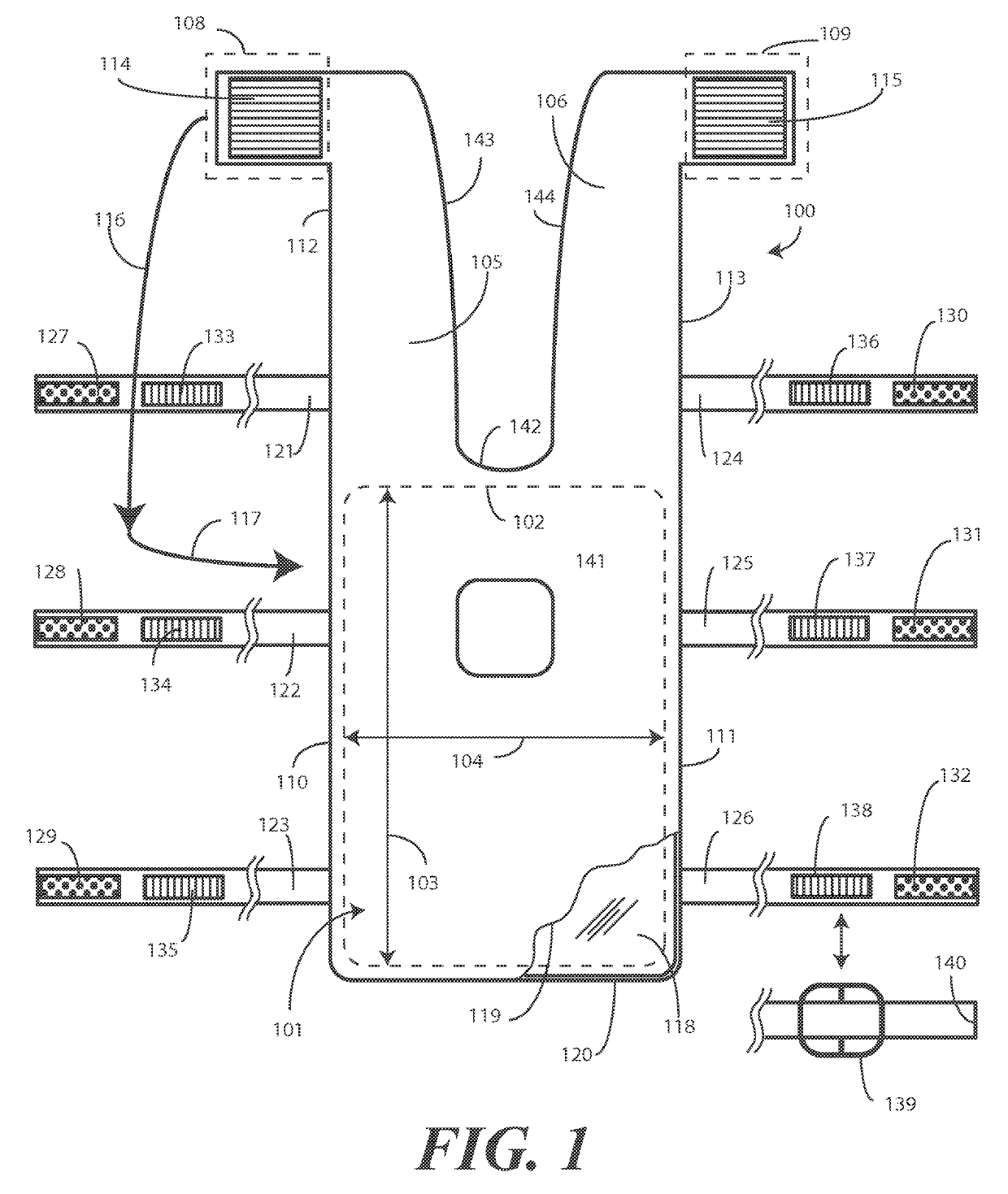
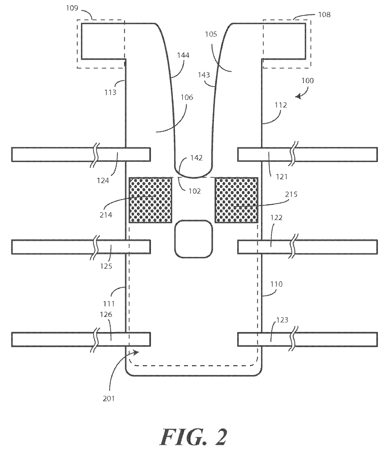
A patient positioner (100) includes a central portion (102) and a pair of shoulder restraints (105,106) extending distally away from a first side (107) of the central portion. Each shoulder restraint can terminate at an attachment area (108,109). Each attachment area can comprise fastener (114,115). Complementary fasteners (214,215) can be disposed on the central portion (102). The shoulder restraints can then be folded (116) about a patient's shoulders, with the fasteners attaching to the complementary fasteners. A plurality of securement straps (121,122,123,124,125,126) configured to attach the patient positioner to a procedure table (701) can extend distally from the second side (110) and the third side (111) of the central portion, respectively.

Description

BACKGROUND[0001]Technical Field[0002]This invention relates generally to a medical accessory, and more particularly to a patient positioner suitable for use during surgery.[0003]Background Art[0004]During a medical procedure, such as a surgical procedure, a patient is placed on a procedure table. In many procedures, a patient positioner is used to retain the patient in a specific location or position on the procedure table. For example, in some abdominal or other surgical procedures, the tilt angle of the procedure table is changed such that the patient's pelvis is above the head so as to allow gravity to assist in moving organs not involved in the procedure away from the procedure site. Such a position is commonly referred to as the “Trendelenburg” position after the German surgeon Freidrich Trendelenburg. In addition to facilitating the gravitational movement of organs away from the procedure site, the Trendelenburg position provides an advantageous field of view of the surgeon du...

Claims


Application Information

Patent Timeline
Patent Type & Authority Patents(United States)
IPC IPC(8): A61F5/37A61G13/04A61G13/12A61G7/005A61G7/057
CPCA61G13/04A61G13/1255A61G2210/90A61G7/057A61G7/005A61G2203/46A61F5/3784
Inventor CHUA, MARK SPENCER G.
Owner MEDLINE IND LP
Learn More