
Coupling system

a technology of coupling system and coupling device, which is applied in the direction of metal-working feeding device, metal-working apparatus, manufacturing tools, etc., can solve the problem of unsatisfactory operation of locking device, and achieve the effect of simple kinematics

Active Publication Date: 2019-10-01
LUGWIG EHRHARDT GMBH
View PDF19 Cites 0 Cited by
  • Summary
  • Abstract
  • Description
  • Claims
  • Application Information

AI Technical Summary

Benefits of technology

The coupling system described in this patent is unique because it allows for unlocking and locking without the need for an external drive. The relative motion of the coupling device and counter-coupling device is all that is required. The system is simple to handle and only requires one linear motion for coupling and uncoupling. When coupled together, the system automatically unlocks using an actuating pin that protrudes out of the coupling device. This makes it easy to place the system on a base surface and start using it. The technical effects of this system are improved ease of handling and simple kinematics.

Problems solved by technology

What is disadvantageous about this known coupling system is the unsatisfactory operation of the locking device.

Method used


Image

  • Coupling system
  • Coupling system
  • Coupling system

Examples


Embodiment Construction

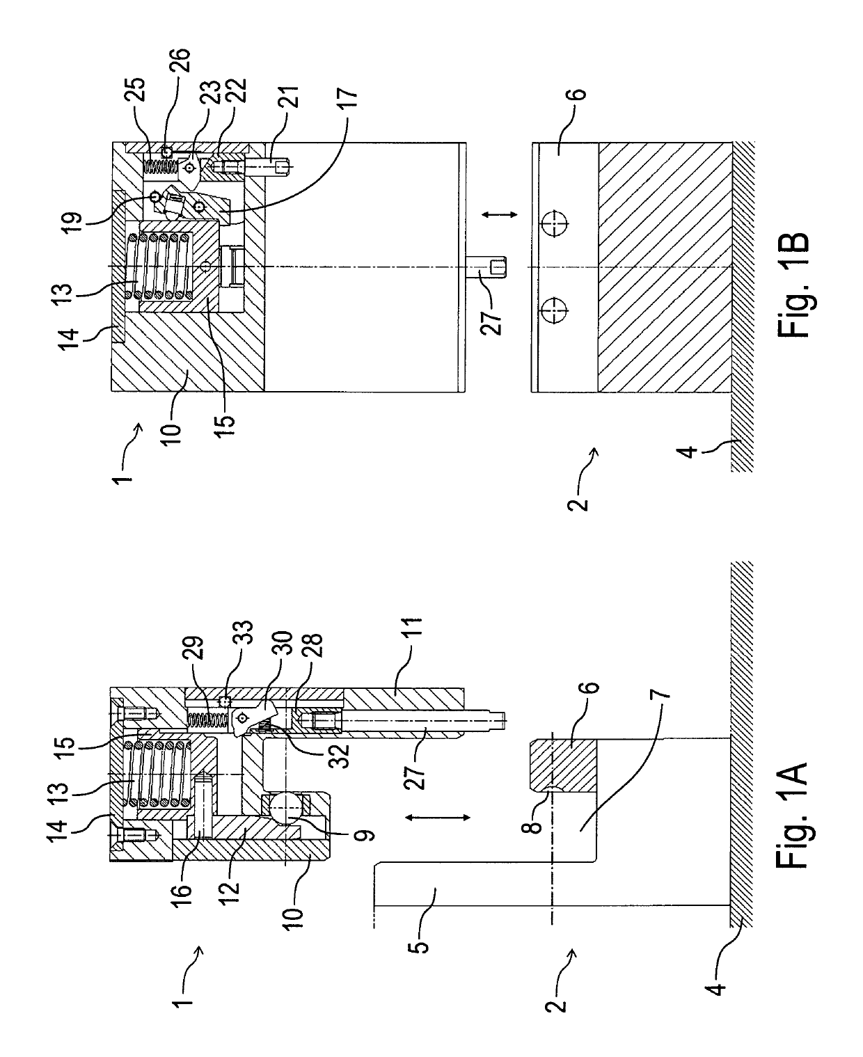
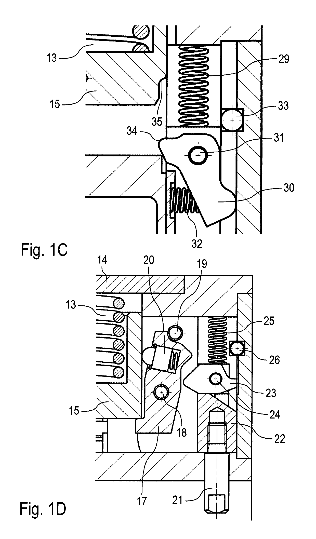
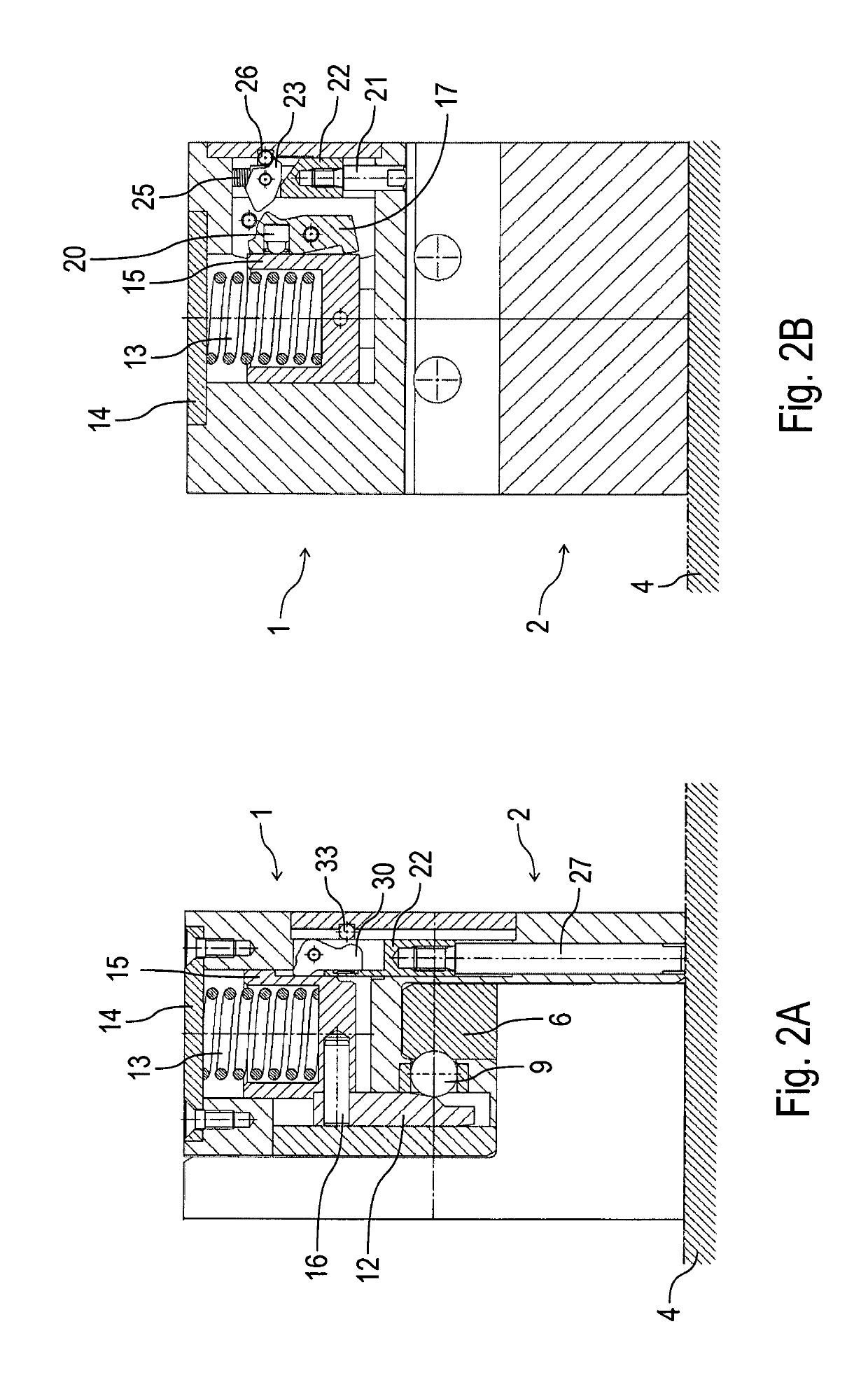
[0039]The drawings show a coupling system according to the invention with a coupling device 1 and a counter-coupling device 2 which can be coupled together.

[0040]The coupling system according to the invention may be used for example instead of the coupling system known from WO 2009 / 135552 A2, in order to detachably couple together a positioning device (not shown) with a gripper rail 3 (cf. FIG. 5). The coupling device 1 is then connected to the positioning device, while the counter-coupling device 2 is connected to the gripper rail 3. The invention is however not restricted to this intended use, but also can be used for other purposes.

[0041]FIGS. 1A-1D show an uncoupled state of the coupling system in which the coupling device 1 is separated and uncoupled from the counter-coupling device 2. The counter-coupling device 2 then rests on a base surface 4, while the coupling device 1 is lifted off upwards.

[0042]The counter-coupling device 2 has on its upper side two crosspieces 5, 6 exte...


PUM


Abstract

The invention relates to a coupling system, in particular for mechanically coupling a positioning mechanism to a gripper rail, comprising a coupling device (1), in particular on a positioning mechanism, a counter coupling device (2), in particular on a gripper rail, wherein the coupling device (1) and the counter coupling device (2) can be selectively coupled together or uncoupled, and a locking device (8-33), which locks the coupling device (1) to the counter coupling device (2) in a locking state and unlocks the coupling device (1) and the counter coupling device (2) in an unlocking state. According to the invention, the locking device (8-33) unlocks and locks solely on the basis of the motion of the coupling device (1) and of the counter coupling device (2) without an external drive.

Description

BACKGROUND OF THE INVENTION[0001]The invention relates to a coupling system for mechanically coupling a coupling device to a counter-coupling device, in particular for mechanically coupling a positioning mechanism on a gripper rail.[0002]A coupling system of this type is known for example from WO 2009 / 135552 A1, and in a mechanical press serves to connect a positioning device detachably to a gripper rail. The coupling system in this case has a locking device which is capable of locking a coupling device connected to the positioning device to a counter-coupling device connected to the gripper rail. The locking in this case takes place by means of locking balls, which are either pressed into a locking position or released by an axially displaceable tensioning pin. The tensioning pin in such case therefore has to be displaced axially for locking or unlocking. A pivotable actuating lever serves for this, which lever turns a gear wheel which engages in corresponding toothing in the tensi...

Claims


Application Information

Patent Timeline
Patent Type & Authority Patents(United States)
IPC IPC(8): B21D43/05F16B1/04
CPCF16B1/04B21D43/057B21D43/055
Inventor GROSCHE, FRANK
Owner LUGWIG EHRHARDT GMBH
Learn More