Liquid ejecting apparatus and liquid refilling container

a technology of liquid ejecting apparatus and liquid refilling container, which is applied in the direction of printing, other printing apparatus, etc., can solve the problems of cumbersome check operation and need for much time for operation, and achieve the effect of convenient refilling

Inactive Publication Date: 2019-10-01
CANON KK
View PDF73 Cites 17 Cited by
  • Summary
  • Abstract
  • Description
  • Claims
  • Application Information

AI Technical Summary

Benefits of technology

[0005]An object of the present invention is to provide a liquid ejecting apparatus that enables a liquid storage container to be properly and easily refilled with a liquid from a liquid refilling container without causing color mixture in the liquid storage container.
[0009]The aspects of the present invention enables the liquid storage container to be properly and easily refilled with the liquid from the liquid refilling container without causing color mixture in the liquid storage container.

Problems solved by technology

Thus, disadvantageously, the user needs to refill the ink tank with ink while checking a plurality of points such as the ink refilling port on the ink refilling container and the protrusions and holes on the ink refilling container, leading to a cumbersome check operation and the need for much time for the operation.

Method used


Image

  • Liquid ejecting apparatus and liquid refilling container
  • Liquid ejecting apparatus and liquid refilling container
  • Liquid ejecting apparatus and liquid refilling container

Examples


first embodiment

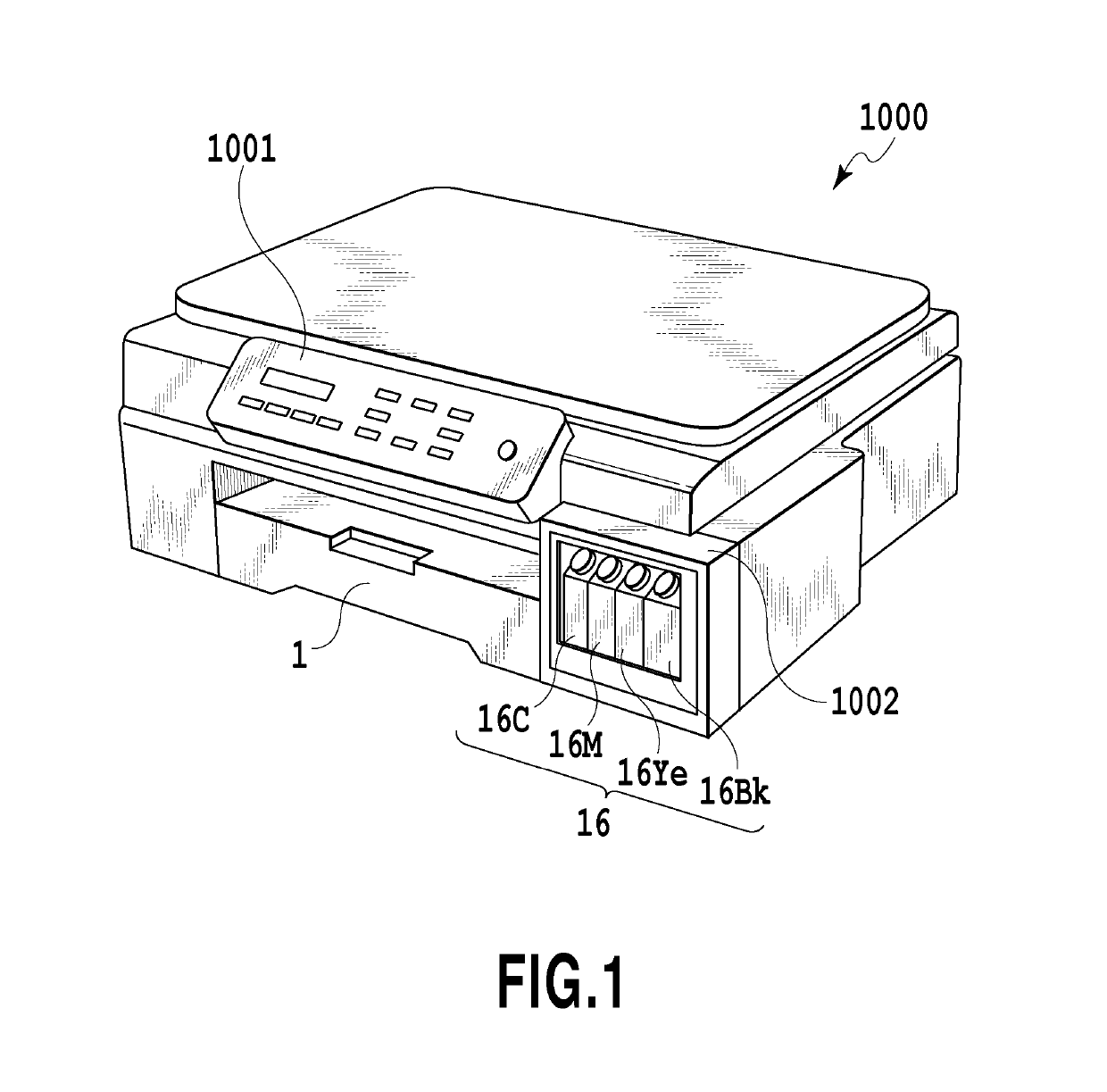
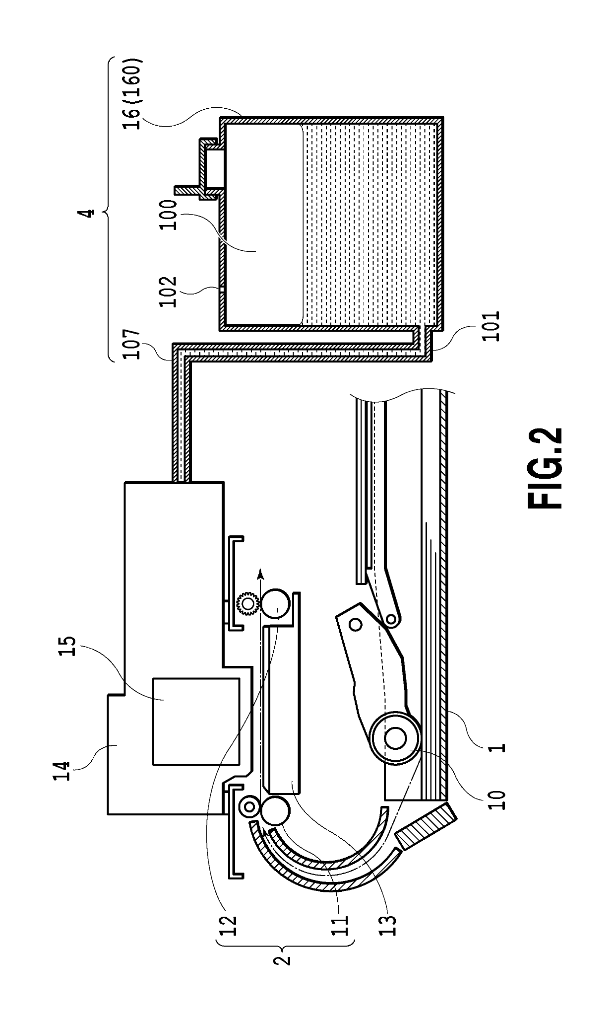
[0032]FIG. 1 is a perspective view illustrating a mechanical unit of an ink jet printing apparatus 1000 (hereinafter referred to as a printing apparatus) in an embodiment of the present invention. FIG. 2 is a longitudinal side view schematically illustrating a configuration of an essential part of the printing apparatus 1000. The mechanical unit mainly includes a first feeding unit 1, a second feeding unit 2, a printing unit 3, and a liquid supply unit 4. In the specification, “ink” is used as a general term for a liquid such as a printing liquid, a fixation treatment liquid, or a resist.

[0033]The first feeding unit 1 uses a feeding roller 10 to separate a print medium from a bundle of print media and feeds the print medium to the second feeding unit 2. The second feeding unit 2 is provided downstream of the first feeding unit 1 in a conveying direction to convey the print medium fed from the feeding roller 10, using a conveying roller 11, a discharging roller 12, and the like. A pl...

second embodiment

[0049]In the first embodiment, even in a case where the protruding portions of the ink tank 16 are not fitted into the recessed portions of the ink refilling container 20, the sealing material may be peeled off from the ink pour-out port 23 in the ink refilling container 20, and the ink tank 16 may be forcibly refilled with ink that is incompatible with the ink tank 16. Thus, a liquid ejecting apparatus in a second embodiment is configured such that ink is not injected into the ink tank 16 unless the recessed portions 24a, 24b of the ink refilling container 20 are fitted over the protruding portions 17a, 17b of the ink tank 16.

[0050]FIG. 7A and FIG. 7B are perspective views illustrating characteristic portions of the second embodiment. FIG. 8A and FIG. 8B are diagrams illustrating operations of a part of the liquid ejecting apparatus including the portions illustrated in FIG. 7A and FIG. 7B. In the figures, the same portions as those in the first embodiment or portions corresponding...

third embodiment

[0054]Now, a third embodiment of the liquid ejecting apparatus according to the present invention will be described with reference to FIGS. 9 to 15A and 15B. FIG. 9 is a perspective view illustrating the liquid ejecting apparatus in the third embodiment. FIG. 10A is a plan view illustrating a part of an ink tank serving as an ink storage container. FIG. 10B is a plan view illustrating a part of an ink refilling container serving as a liquid refilling container. FIG. 11 is a plan view illustrating a plurality of types of ink tanks. FIG. 12 is a plan view illustrating a plurality of types of ink refilling containers.

[0055]The liquid ejecting apparatus in the present embodiment includes an ink tank 160 and an ink refilling container 200 illustrated in FIG. 9. Also in the third embodiment, ink stored in a liquid storage space in the ink tank 160 is fed to the print head 15 via the ink channel 101 and the ink supply tube 107 as in the case of the first embodiment (see FIG. 2).

[0056]As il...


PUM


Abstract

An object is to provide a liquid ejecting apparatus that enables a liquid storage container to be properly and easily refilled with a liquid from a liquid refilling container without causing color mixture in the liquid storage container. The liquid ejecting apparatus includes liquid storage containers each configured to feed the liquid to a liquid ejecting portion and liquid refilling containers each configured to refill the liquid storage container with the liquid. A first fitting unit is provided around a liquid injection port in each of the liquid storage containers. A second fitting unit is provided around a liquid pour-out port in each of the liquid refilling containers. The second fitting unit is fitted to the first fitting unit to enable the liquid to be delivered from the liquid pour-out port to the liquid injection port.

Description

BACKGROUND OF THE INVENTIONField of the Invention[0001]The present invention relates to a liquid refilling container from which a liquid is fed to a liquid ejecting portion and a liquid ejecting apparatus including the liquid refilling container.Description of the Related Art[0002]As a liquid ejecting apparatus that ejects a liquid for printing, an ink jet printing apparatus is known. In the ink jet printing apparatus, ink is ejected from a print head serving as a liquid ejecting portion to print a print medium. The ink is fed to the print head, for example, from an ink tank provided in the ink jet printing apparatus, via a channel.[0003]An ink jet printing apparatus disclosed in Japanese Patent Laid-Open No. 2003-305865 is provided with a plurality of print heads to eject a plurality of types of ink and with a plurality of ink tanks corresponding to the print heads. To refill the ink tanks with ink, a user injects ink into an ink injection port formed in each of the ink tanks, thro...

Claims


Application Information

Patent Timeline
Patent Type & Authority Patents(United States)
IPC IPC(8): B41J2/175B41J2/21B41J2/03B41J2/01
CPCB41J2/17533B41J2/17506B41J2/03B41J2/2125B41J2/01B41J2/17503B41J2/175B41J2/21B41J2/1753B41J2/17509B41J2/1752B41J2/17523B41J2/17553B41J29/13
Inventor OKUDE, KYOSHIROKOMORI, MASATERUKOSHIMIZU, MASATOSAEKI, TSUYOSHIKIMURA, YUKIMICHIKAWANISHI, MASAHIROMATSUURA, MASAAKIYOKOI, KATSUYUKISHIBA, AKIRASHIMAMURA, RYOYOSHII, KAZUYAIKEBE, NORIHIROMIYASHITA, TAKEHOYAMAMURO, TOMOKIARAI, ATSUSHIOHIRA, MASATOSHIORIHARA, TATSUAKIOKUHARA, HIROFUMIMATSUSHITA, KAZUMASAFURUYA, MISATO
Owner CANON KK
Why Eureka
Try Eureka