
Loading machine for cartridges with a metal case

a metal case and cartridge technology, applied in the direction of weapons, ammunition, weapons, etc., can solve the problems of destroying the case itself, and destroying the cartridge perfectly coaxially

Active Publication Date: 2019-10-15
EMG INC
View PDF55 Cites 1 Cited by
  • Summary
  • Abstract
  • Description
  • Claims
  • Application Information

AI Technical Summary

Benefits of technology

The present invention describes a loading machine that can automatically ensure that the case and working tools used to load and work on cartridges are perfectly aligned, which helps protect the components of the cartridge from deformation that could affect its efficiency. Additionally, the invention provides a productive and efficient loading machine that can easily change the caliber of cartridges being produced.

Problems solved by technology

The main drawbacks of these loading machines for cartridges with metal cases concern the difficulty in keeping the cartridges perfectly coaxial with the respective filling means, during the various conveying and loading steps.
A non-perfect alignment between the axis of the cartridge, particularly of the metal case, and the vertical downward axis of the working tool risks ruining and damaging the case itself during filling, for example there may occur a lateral deformation of the case or its mouth may be crushed.
Similarly, there may disadvantageously be a deformation of the ball during its positioning on the case, or its positioning may be inclined with respect to the axis of the case, which could compromise the trajectory of the bullet when fired.
Further drawbacks relate to the long machine preparation times due to possible changes in the caliber of the cartridges being produced.
Disadvantageously, all these operations require a great deal of time, forcing the machine to be out of service for long periods, with consequent slow-down and reduction in productivity, causing economic losses.
Operators also need to use different instruments for measuring and checking the alignment and respect for the correct distance between the machine components, with obvious complications in terms of tuning and registry before the re-start of work.

Method used


Image

  • Loading machine for cartridges with a metal case
  • Loading machine for cartridges with a metal case
  • Loading machine for cartridges with a metal case

Examples


Embodiment Construction

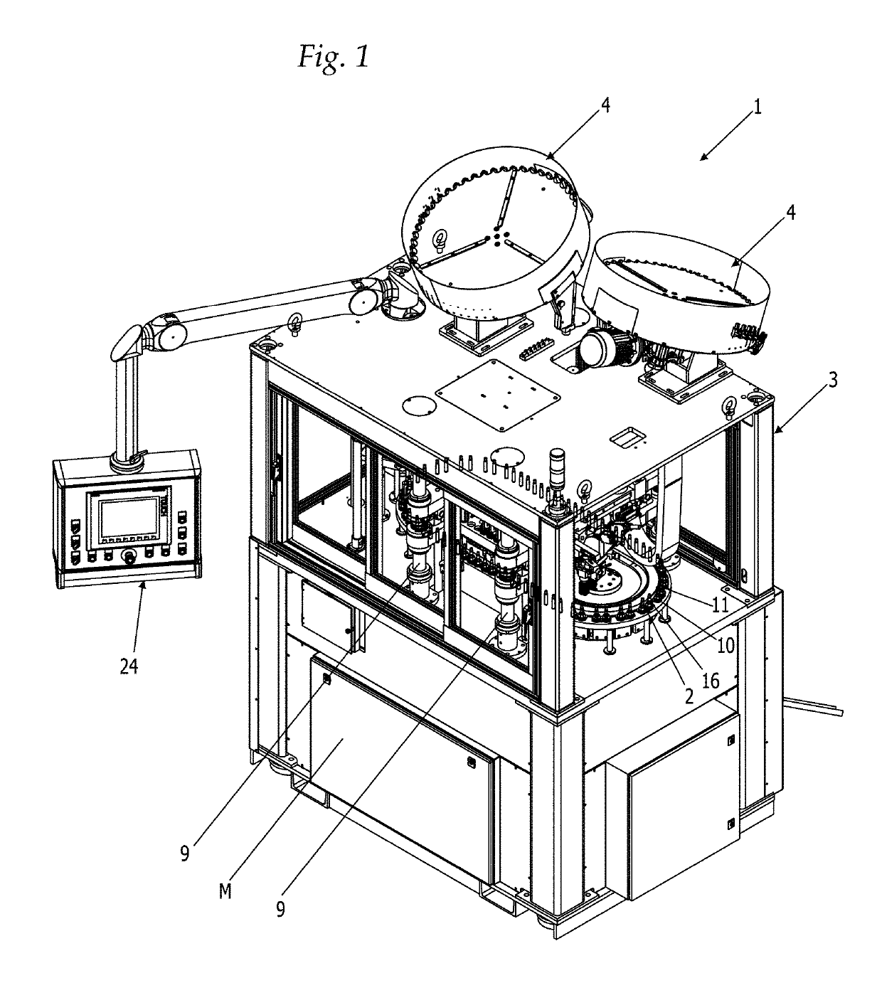
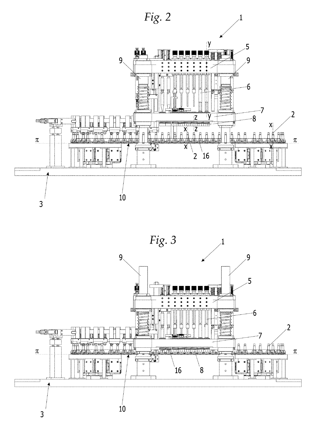
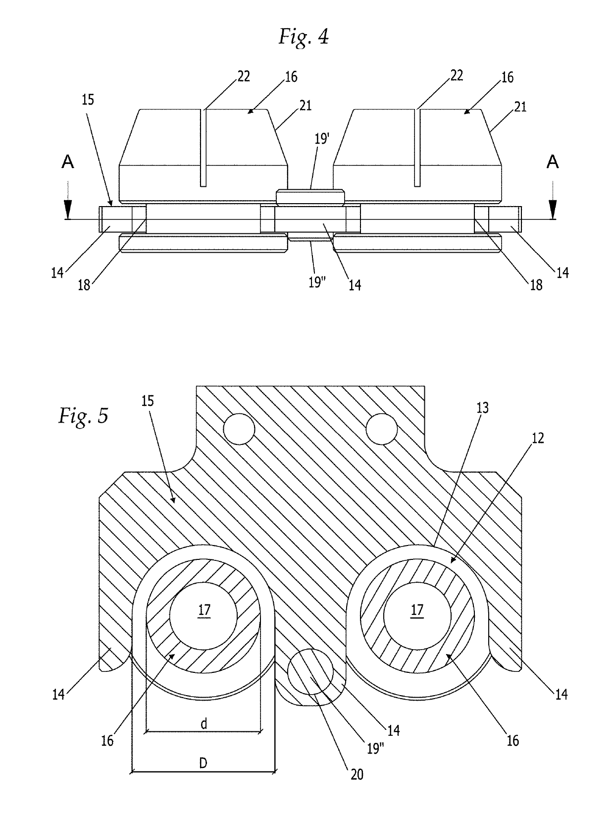
[0056]With reference to FIGS. 1-3, there is illustrated a loading machine 1 for cartridges with a metal case 2, adapted for the preparation and production of ammunition with a single ogival ball used in the sporting and military sector.

[0057]Said machine 1 essentially comprises:[0058]a frame structure 3 on which are provided feed means 4 for a plurality of cases 2 having a given caliber c and a longitudinally extending axis x, and feed means for a plurality of ogival balls and for gunpowder;[0059]a first operating beam 5 having an alternating vertical translation movement, provided with working tools 6 having a vertical axis y, adapted to load and process said cases 2;[0060]feed and conveying means of said cases 2 during loading;[0061]means for ejecting the loaded cartridges;[0062]motor means M for activation of kinematic mechanisms;[0063]a control unit 24 adapted to supervise all functions of the machine 1.

[0064]Said machine 1 further comprises a second operating beam 7, also havin...


PUM


Abstract

Disclosed is a loading machine for cartridges with a metal case including a frame structure; a feed unit for a plurality of cases having a longitudinally extending axis; a first operating beam having an alternating vertical translation movement, provided with working tools having a vertical axis, adapted to load the cases; feed and a conveyor of the cases and element for ejecting the loaded cartridges; a motor and a control unit. The feed unit includes a race and a conveyor guide comb defining a plurality of seats, containing the cases conveying them along the race. The conveyor guide includes bushings, each including at least a first conical surface and a hole to house one of the bushings and being housed in one of the seats. The machine includes a second operating beam, having an alternating vertical translation movement, provided with a plurality of hollow centering cylinders having a vertical axis.

Description

[0001]The present invention relates to the sector of lines for the production and loading of cartridges, and in particular relates to a loading machine for cartridges with a metal case, equipped to receive the empty cases provided with a primer, and to prepare them and provide them with the components needed to produce cartridges that are ready for use.BACKGROUND OF THE INVENTION[0002]According to known art, loading machines for cartridges with a metal case substantially comprise a frame structure, feed means for metal cases, for ogival balls and for gunpowder, an operating beam supporting accessory means for in-line loading and processing of said cartridges, feed and conveying means of the cartridges during loading, and means for ejecting the loaded cartridges.[0003]According to known art, the cartridge feed and conveying means generally comprise a race on which are the metal cases are positioned and slid, resting on their base with their open end pointing upwards, wherein the acce...

Claims


Application Information

Patent Timeline
IPC IPC(8): F42B33/00
CPCF42B33/002F42B33/001
Inventor GATTI, GIORGIO
Owner EMG INC
Learn More